

Needle path planning in semiautonomous and teleoperated robot-assisted epidural anaesthesia procedure: A proof of concept
- PMID: 35699156
- PMCID: PMC9787351
- DOI: 10.1002/rcs.2434
Needle path planning in semiautonomous and teleoperated robot-assisted epidural anaesthesia procedure: A proof of concept
Abstract
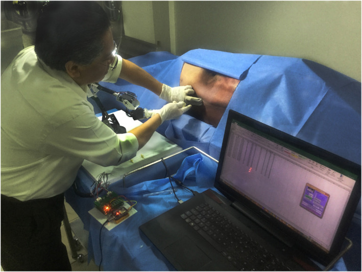
Background: Epidural anaesthesia is a Percutaneous Procedure (PP) which plays a crucial role in surgical procedures, where accurate needle insertion is still challenging. The objective of this work is to present a Tuohy needle path planning, which allows an anaesthesiologist to drive semiautonomously, with the assistance of a teleoperated robot, the tip of the needle during this PP.
Methods: We capture, analysed and modelled the anaesthetist hands' motion during the execution of this procedure, by synthetising, programing and simulating a parametrised and normalised kinematic constrains dependent on an insertion variable in a virtual robot.
Results: Two preoperative path planning models were obtained, which provide a teleoperated robot with kinematic constraints to semiautonomously drive a Tuohy needle in the epidural anaesthesia procedure.
Conclusions: A semiautonomous robot can assist in the execution of this PP using the kinematic constraints obtained from the study of the movement of a specialist's hands.
Keywords: epidural anaesthesia procedure; needle path planning; percutaneous procedure; semiautonomous robot.
© 2022 The Authors. The International Journal of Medical Robotics and Computer Assisted Surgery published by John Wiley & Sons Ltd.
Conflict of interest statement
The authors have no conflicts of interest to declare that are relevant to the content of this article.
Figures


References
-
- Abolhassani N, Patel R, Moallem M. Needle insertion into soft tissue: a survey. Med Eng Phys. 2007;29(4):413‐431. - PubMed
-
- Kang H, Wen JT. Autonomous suturing using minimally invasive surgical robots. In: Proceedings of the 2000 IEEE International Conference on Control Applications. Conference Proceedings (Cat. No.00CH37162). IEEE; 2000:742‐747.
-
- Chow D‐L, Newman W. Improved knot‐tying methods for autonomous robot surgery. In: 2013 IEEE International Conference on Automation Science and Engineering (CASE). IEEE; 2013:461‐465.
-
- Ye M, Li W, Chan DTM, Chiu PWY, Li Z. A semi‐autonomous stereotactic brain biopsy robot with enhanced safety. IEEE Rob Autom Lett. 2020;5(2):1405‐1412.
MeSH terms
Grants and funding
LinkOut - more resources
Full Text Sources
Miscellaneous
