. 2022 Jul 1;225(13):jeb244087.
doi: 10.1242/jeb.244087. Epub 2022 Jul 7.

Generating spatiotemporal patterns of linearly polarised light at high frame rates for insect vision research

Affiliations

Generating spatiotemporal patterns of linearly polarised light at high frame rates for insect vision research

Jack A Supple et al. J Exp Biol. .

Abstract

Polarisation vision is commonplace among invertebrates; however, most experiments focus on determining behavioural and/or neurophysiological responses to static polarised light sources rather than moving patterns of polarised light. To address the latter, we designed a polarisation stimulation device based on superimposing polarised and non-polarised images from two projectors, which can display moving patterns at frame rates exceeding invertebrate flicker fusion frequencies. A linear polariser fitted to one projector enables moving patterns of polarised light to be displayed, whilst the other projector contributes arbitrary intensities of non-polarised light to yield moving patterns with a defined polarisation and intensity contrast. To test the device, we measured receptive fields of polarisation-sensitive Argynnis paphia butterfly photoreceptors for both non-polarised and polarised light. We then measured local motion sensitivities of the optic flow-sensitive lobula plate tangential cell H1 in Calliphora vicina blowflies under both polarised and non-polarised light, finding no polarisation sensitivity in this neuron.

Keywords: Electrophysiology; Neuroethology; Neuroscience; Polarisation vision.


Conflict of interest statement

Competing interests The authors declare no competing or financial interests.

Figures

Fig. 1.
Fig. 1.
Dual digital light processing (DLP) stimulation device for projecting moving patterns of polarised light. (A) Images from two DLP projectors are aligned and superimposed. Patterns can be projected with polarised intensity contrasts (DLP1) or non-polarised intensity contrasts (DLP2). Superimposing inverted images from the two DLPs nullifies intensity contrasts. Polariser and neutral density (ND) filters can be exchanged for control experiments. (B) LED luminance equalisation of the two projected images for blue and green light. Polarised (Pol) DLP1 intensities varied sinusoidally with polariser angle as a result of intrinsic DLP polarisation. The lowest uncalibrated luminance [DLP1 green non-polarised (NP)] was designated the calibration target (Calib. target) to which other intensities were matched by adjusting LED currents. (C) To verify temporal synchrony, two squares, one from each projector, were filmed moving along circular trajectories with offset radii. The six panels correspond to the motion of each square along its circular trajectory at 360 Hz. Angular correspondence of each square position indicates that the two projectors are synchronised. (D) Polarimetry of the dual DLP system displaying a polarised dot at 0 deg and 45 deg angle of polarisation (AoP) against a luminance-equalised background of the same colour. From top to bottom: normalised total intensity; degree of linear polarisation (DoLP); AoP; AoP with pixel brightness weighted by the DoLP (low DoLP pixels appear darker than higher DoLP pixels).
Fig. 2.
Fig. 2.
Argynnis paphia photoreceptor receptive fields for polarised and non-polarised light. (A) Receptive fields of polarisation-sensitive blue and green photoreceptors. Receptive fields were measured using non-polarised and polarised bright squares on a dark background (contrast=+1), and polarised objects masked with a bright non-polarised background (contrast=0). Blue: N=3 cells from 2 animals; green: N=3 cells from 2 animals, except for masked polarised objects (N=1; asterisks). (B) Receptive field response maxima (see Fig. S2) for blue-sensitive photoreceptors, normalised to non-polarised (NP) receptive fields (asterisk). Symbols/lines represent the mean of single trials per cell across animals; shaded regions represent 1 s.d. (C) Receptive field response maxima for green-sensitive photoreceptors, as in B. Note N=1 for masked polarised objects (contrast: 0), so there is no s.d.
Fig. 3.
Fig. 3.
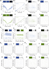
Calliphora vicina H1 cell motion responses to contrast artefacts and polarised light. (A) H1 cell non-polarised control contrast tuning curves for (i) blue and (ii) green light. Both projectors are non-polarised. Contrast is varied from a dark object/bright background (Weber contrast=−1), to a bright object/bright background (Weber contrast=0, i.e. intensity-nullified control condition), to a bright object/dark background (Weber contrast=+1). Data are means±1 s.d., N=7 animals. (B) H1 cell non-polarised local motion sensitivity (LMS) spike rate variance plotted against LMS mean for (i) blue and (ii) green light (same data as in A). Black dashed line represents y=x. (C) Average H1 cell receptive fields for non-polarised bright (contrast=+1) (i) blue and (ii) green moving dots. Positive elevation values correspond to the dorsal visual field. Positive azimuth values correspond to the right visual field. Vector direction represents local preferred direction (LPD), vector length represents relative LMS. Dark vectors represent sampled positions; light vectors are interpolated. Blue: N=6 animals; green: N=5 animals. (D) Average H1 cell receptive fields for non-polarised and intensity contrast-nullified (contrast=0) (i) blue and (ii) green moving dots (same format as in C). Blue: N=6 animals; green: N=5 animals. (E) H1 cell polarisation tuning curves for (i) blue and (ii) green light. Bright (contrast=+1) and intensity contrast-nullified (contrast=0) dots were presented for non-polarised (NP) and polarised conditions at 45 deg AoP increments. 0 deg AoP aligns with the eye equator. Circle and solid line represent contrast=+1. Asterisk and dashed line represent contrast=0. Data are means±1 s.d., N=6 animals. (F) Average H1 cell receptive fields of cells (same as those in G and H) when stimulated with non-polarised bright dots (contrast=+1) for (i) blue and (ii) green light. Vector plot as in C. N=4 animals for each spectral condition. (G,H) Average H1 cell receptive fields of cells in F when stimulated with polarised and intensity contrast-nullified (contrast=0) dots at 45 deg AoP increments for (G) blue and (H) green light. Vector plot as in C. N=4 animals for each spectral condition.

Similar articles

Cited by

References

    1. Bandai, K., Arikawa, K. and Eguchi, E. (1992). Localization of spectral receptors in the ommatidium of butterfly compound eye determined by polarization sensitivity. J. Comp. Physiol. A 171, 289-297. 10.1007/BF00223959 - DOI
    1. Belušič, G., Ilić, M., Meglič, A. and Pirih, P. (2016). A fast multispectral light synthesiser based on LEDs and a diffraction grating. Sci. Rep. 6, 1-9. 10.1038/s41598-016-0001-8 - DOI - PMC - PubMed
    1. Belušič, G., Ilić, M., Meglič, A. and Pirih, P. (2021). Red-green opponency in the long visual fibre photoreceptors of brushfoot butterflies (Nymphalidae). Proc. R. Soc. B 288, 20211560. - PMC - PubMed
    1. Blum, M. and Labhart, T. (2000). Photoreceptor visual fields, ommatidial array, and receptor axon projections in the polarisation-sensitive dorsal rim area of the cricket compound eye. J. Comp. Physiol. A Sensory, Neural Behav. Physiol. 186, 119-128. - PubMed
    1. Borst, A., Haag, J. and Reiff, D. F. (2010). Fly motion vision. Annu. Rev. Neurosci. 33, 49-70. 10.1146/annurev-neuro-060909-153155 - DOI - PubMed

Publication types