. 2022 May 26:12:847250.
doi: 10.3389/fonc.2022.847250. eCollection 2022.

Endoscopic Endonasal Supraoptic and Infraoptic Approaches for Complex "Parasuprasellar" Lesions: Surgical Anatomy, Technique Nuances, and Case Series

Affiliations

Endoscopic Endonasal Supraoptic and Infraoptic Approaches for Complex "Parasuprasellar" Lesions: Surgical Anatomy, Technique Nuances, and Case Series

YouYuan Bao et al. Front Oncol. .

Abstract

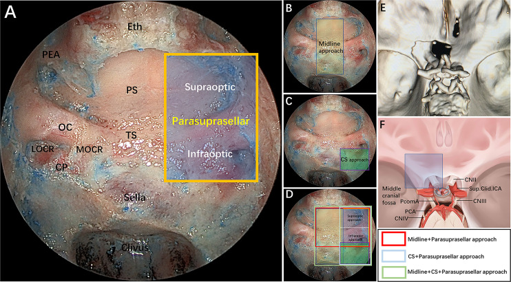
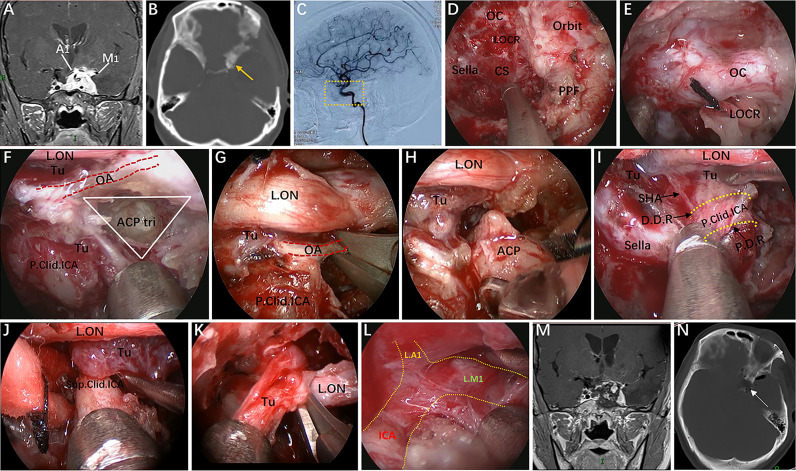
Objective: The surgical management of lesions involving the lateral area of the suprasellar region, including the lateral aspect of the planum sphenoidale and the tight junction region of the optic canal (OC), anterior clinoid process (ACP), and internal carotid artery (ICA) and its dural rings, is extremely challenging. Here, these regions, namely, the "parasuprasellar" area, are described from the endonasal perspective. Moreover, the authors introduce two novels endoscopic endonasal supraoptic (EESO) and endoscopic endonasal infraoptic (EEIO) approaches to access the parasuprasellar area.

Methods: Surgical simulation of the EESO and EEIO approaches to the parasuprasellar area was conducted in 5 silicon-injected specimens. The same techniques were applied in 12 patients with lesions involving the parasuprasellar area.

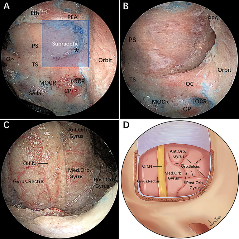
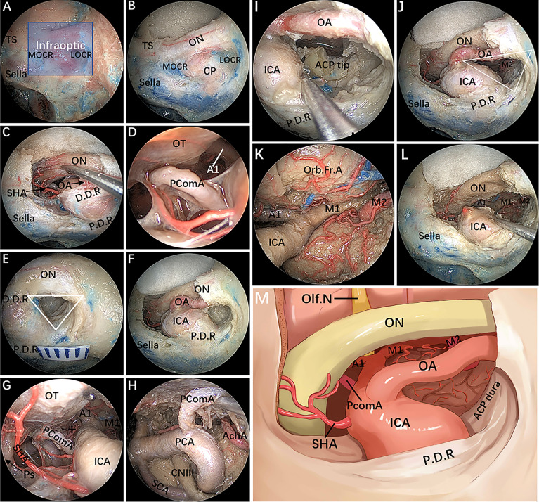
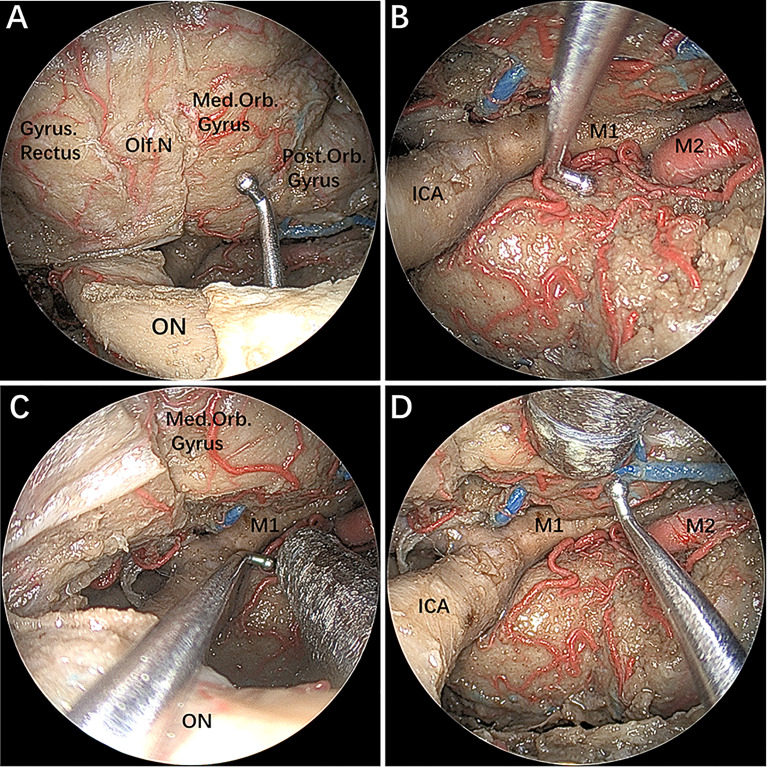
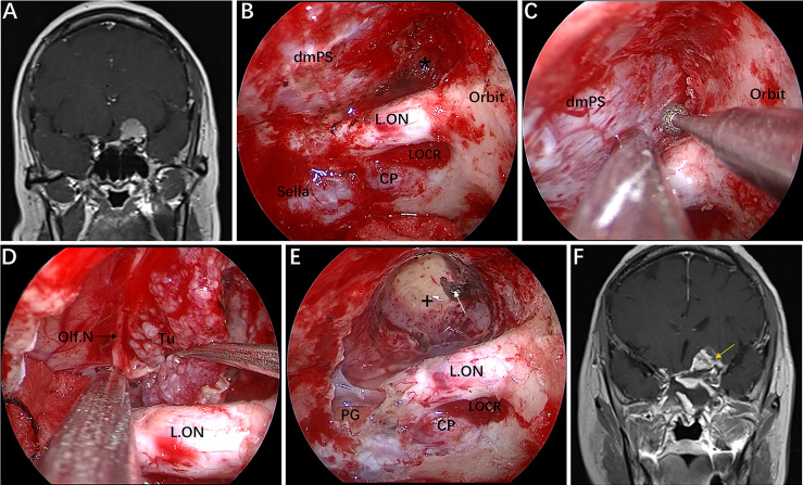
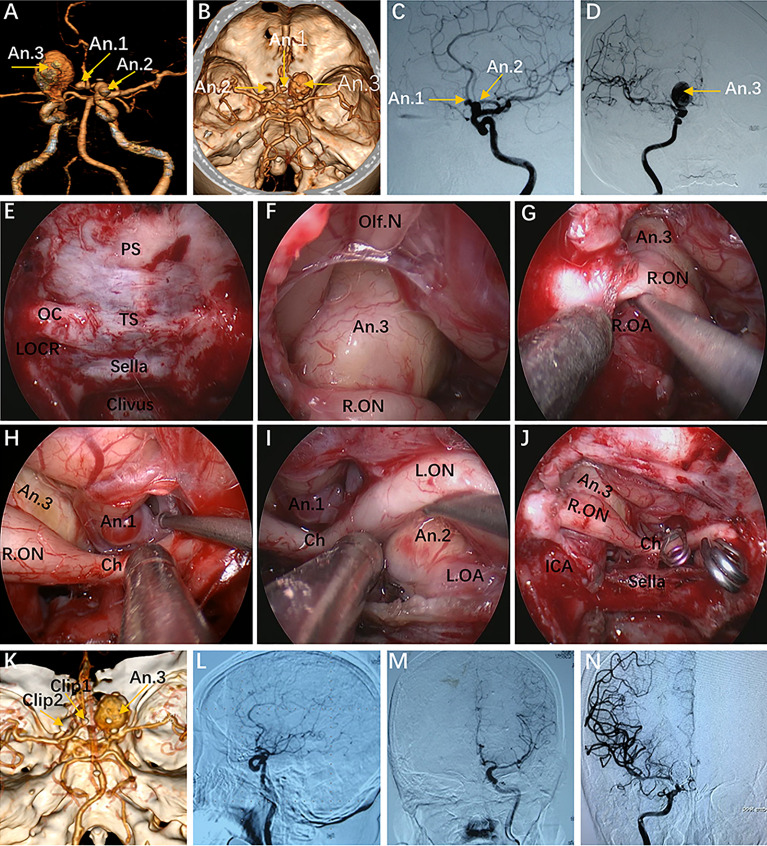
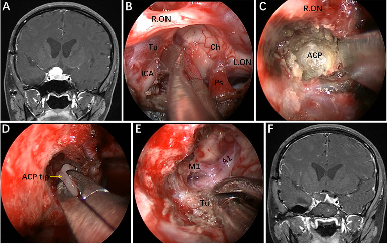
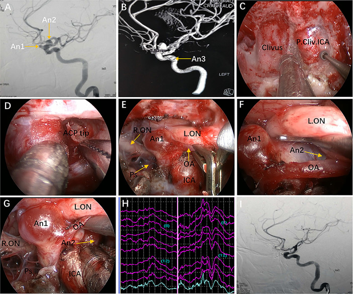
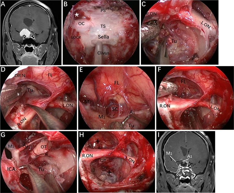
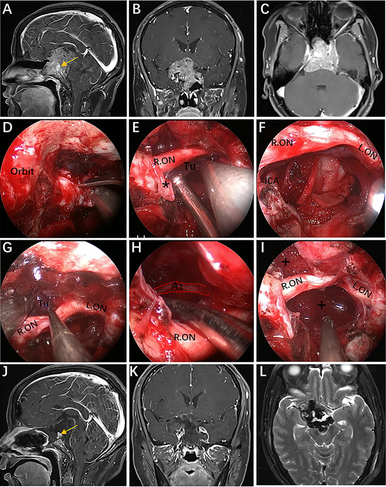
Results: The EESO approach provided excellent surgical access to the lateral region of the planum sphenoidale, which corresponds to the orbital gyrus of the frontal lobe. With stepwise bone (OC, optic strut and ACP) removal, dissociation of the ophthalmic artery (OA) and optic nerve (ON), the EEIO approach enables access to the lateral region of the supraclinoidal ICA. These approaches can be used independently or in combination, but are more often employed as a complement to the endoscopic endonasal midline and transcavernous approaches. In clinical application, the EESO and EEIO approaches were successfully performed in 12 patients harboring tumors as well as multiple aneurysms involving the parasuprasellar area. Gross total and subtotal tumor resection were achieved in 9 patients and 1 patient, respectively. For two patients with multiple aneurysms, the lesions were clipped selectively according to location and size. Visual acuity improved in 7 patients, remained stable in 4, and deteriorated in only 1. No postoperative intracranial infection or ICA injury occurred in this series.

Conclusions: The EESO and EEIO approaches offer original treatment options for well-selected lesions involving the parasuprasellar area. They can be combined with the endoscopic endonasal midline and transcavernous approaches to remove extensive pathologies involving the intrasellar, suprasellar, sphenoid, and cavernous sinuses and even the bifurcation of the ICA. This work for the first time pushes the boundary of the endoscopic endonasal approach lateral to the supraclinoidal ICA and ON.

Keywords: anterior clinoid process; endoscopic endonasal approach; internal carotid artery; optic canal; parasuprasellar area; surgical technique.


Conflict of interest statement

The authors declare that the research was conducted in the absence of any commercial or financial relationships that could be construed as a potential conflict of interest.

Figures

Figure 1
Figure 1
(A) Endoscopic endonasal view of our proposed parasuprasellar area and its surrounding essential anatomical structures. The parasuprasellar area is delineated by the yellow quadrangular space, which is limited medially by the medial edge of the MOCR, laterally by the lateral edge of the LOCR, superiorly by the PEA, and inferiorly by the inferior edge of the MOCR and LOCR. In addition, as bounded by the optic nerve, it can be divided into supraoptic and infraoptic regions. (B–D) Illustration showing different combinations of surgical modules in both midline (transsellar/transtuberculum/transplanum approach) and/or lateral (transcavernous and parasuprasellar approach) planes. Note that the parasuprasellar approach includes supraoptic and infraoptic approaches. The various combinations of endoscopic corridors are indicated with different quadrangular colors (figure in the lower right corner). Red marks the combination of the endoscopic endonasal midline approach and parasuprasellar approach; blue represents the combination of the transcavernous approach and parasuprasellar approach; green shows the combination of the midline approach, transcavernous approach and parasuprasellar approach. (E) Three-dimensional (3D) reconstruction of a postoperative fine-slice CT scan showing the extent of bone removal through the supraoptic and infraoptic approaches. (F) Artistic illustration demonstrating maximum bone removal (blue square) in the parasuprasellar area via the supraoptic and infraoptic approach. Eth, cribriform plate of the ethmoid; PEA, posterior ethmoidal artery; PS, planum sphenoidale; OC, optic canal; TS, tuberculum sellae; MOCR, medial optocarotid recess; LOCR, lateral optocarotid recess; CP, carotid protuberance; CS, cavernous sinus; CN II, optic nerve; CN III, oculomotor nerve; CN IV, trochlear nerve; PcomA, posterior communication artery; Sup.Clid. ICA, supraclinoidal internal carotid artery; PCA, posterior cerebral artery. The figure is available in color only online.
Figure 2
Figure 2
Endoscopic endonasal supraoptic (EESO) approach: stepwise dissection to the supraoptic region in a colored silicone-injected cadaveric specimen. (A) Panoramic view of the sphenoid sinus floor with its anatomical landmarks. The blue quadrangular zone marks the supraoptic region, and the black asterisk represents the supraoptic recess. (B) A closer view of the supraoptic region after removal of the medial portion of the lesser sphenoid wing and OC unroofing. (C) After removing the bone and dura mater lateral to the planum sphenoidale, the gyrus rectus, olfactory nerve, medial orbital gyrus, anterior orbital gyrus and post orbital gyrus of the frontal lobes were exposed, viewed with a 0° endoscope. (D) Artistic illustration demonstrating the contents of the supraoptic region that can be reached via the EESO approach. Olf. N, olfactory nerve; Med.Orb. Gyrus, medial orbital gyrus; Ant.Orb. Gyrus, anterior orbital gyrus; Post.Orb. Gyrus, post orbital gyrus. The figure is available in color only online.
Figure 3
Figure 3
Endoscopic endonasal infraraoptic (EEIO) approach: stepwise dissection to the infraoptic region in a colored silicone-injected cadaveric specimen. (A) The main anatomical landmarks in the infraoptic region (blue zone) are shown. (B) Removal of the anterior wall of the OC in a medial-lateral direction up the orbit apex. (C) The dura overlying the intracranial ON was incised longitudinally to expose the origin of the OA; the diaphragm was incised toward the medial part of the DDR, and SHA and its branches were exposed. (D) A closer view shows more subdural contents, including the PcomA, OT and A1 segments of the anterior cerebral artery. (E) Drilling of the optic strut and showing the ACP triangle. (F) The DDR and ON sheath are opened to further safely dissociate the OA and ON. (G, H) The subdural neurovascular structures were explored again by gently lifting of the ipsilateral ON. The main structures are identified, including the PcomA, pituitary stalk, AchA and its branches (black plus sign) into the anterior perforating substance in the crural cistern, the CNIII passing between the PCA and SCA into the cavernous sinus, and the bifurcation of the ICA. (I) The base and tip of the ACP can be further removed by gentle lifting of the OA or medial mobilization of the paraclinoidal ICA. (J) The ACP triangular is further enlarged. (K) The sylvian cistern was visible, and the ICA bifurcation was exposed between the frontal and temporal lobes; more laterally, the middle cerebral artery (MCA) bifurcation was observed at the level of its insular portion. (L) The OA was transected, and the operation space of the EEIO corridor was further enlarged. (M) Artistic illustration showing the main contents of the infraoptic region that can be reached via the EEIO approach. Note the ON has been slightly elevated. ON = optic nerve; OA = ophthalmic artery; SHA = superior hypophyseal artery; D.D.R, distal dural ring; P.D.R, proximal dural ring; ICA, internal carotid artery; OT, optic tract; AchA, anterior choroidal artery; SCA, superior cerebellar artery; Orb.Fr.A, orbital frontal artery; ACP, anterior clinoid process; M1, sphenoidal segment of the middle cerebral artery; M2, insular segment of the middle cerebral artery. The figure is available in color only online.
Figure 4
Figure 4
(A–D) The instruments demonstrating a combined supraoptic and infraoptic approach to access the parasuprasellar area. The figure is available in color only online.
Figure 5
Figure 5
Case 1, a 56-year-old woman, presented with a 1-year history of dizziness and progressive left visual loss for more than 1 month. (A) Preoperative coronal Gd-enhanced MRI showing a left ACP meningioma. (B–E) Intraoperative images. (B) Exposure of the lateral dura of the planum sphenoidale and supraoptic recess (black asterisk). (C) Drilling the roof wall of the optic canal and supraoptic recess in a medial-to-lateral direction toward the body of the lesser sphenoid wing. (D) Separation of the tumor from the olfactory nerve through the supraoptic approach. (E) Final endoscopic view after complete tumor removal. The white arrow represents the severed posterior ethmoidal artery. (F) Postoperative coronal MRI showing total tumor removal. The yellow arrow represents the autologous fat used during the operation. + = tumor cavity. The figure is available in color only online.
Figure 6
Figure 6
Case 10, a 62-year-old woman, presented with visual loss for 2 months. (A, B) Preoperative CT angiography (A) and a 3-D reconstruction image (B) showing an Acom aneurysm (An1), a left praclinoid aneurysm (An2), and a large right paraclinoid aneurysm (An3). (C, D) Anteroposterior view (C) and lateral view (D) of bilateral internal carotid artery (ICA) injection of digital subtraction angiography (DSA) confirming an Acom aneurysm, a left praclinoid aneurysm, and a large right paraclinoid aneurysm. (E–J) Intraoperative images. (E) Endoscopic view of the skull base showing important bony landmarks. (F, G) Intraoperative image demonstrating an aneurysm body with a thrombus above the right optic nerve that cannot be clipped through an endonasal approach. (H, I) Exposure to the Acom aneurysm (H) and left paraclinoid aneurysm (I). (J) Intraoperative picture showing that both aneurysms were clipped successfully after proximal control. (K) Postoperative CT angiography confirmed the patency of the bilateral A2 and distal ICA. (L, M) Postoperative lateral view (L) and anteroposterior view (M) of left ICA injection of DSA, revealing complete obliteration of An1 and An2. (N) Postoperative anteroposterior view of right ICA injection of DSA, showing complete obliteration of the An3 after second-stage coiling. An, aneurysm; R.OA, right ophthalmic artery; L.OA, left ophthalmic artery; Ch, optic chiasm. The figure is available in color only online.
Figure 7
Figure 7
Case 2, A 25-year-old woman presented with headache and decreased vision in her right eye for 6 months. (A) Preoperative coronal Gd-enhanced MRI demonstrating a right recurrent ACP meningioma. (B) Removal of the tumor on the medial and upper parts of the supraclinoidal ICA. (C, D) Removal of the ACP invaded by the tumor. (E) Separation of tumor adhering to the bifurcation of the ICA through the infraoptic corridor. (F) Postoperative MRI showing total tumor removal. Tu = tumor; Ps = pituitary stalk; ACP = anterior clinoid process. Some panels (7A, D, F) of the figure have been published in Journal of Neurosurgery. Published with permission. The figure is available in color only online.
Figure 8
Figure 8
Case 9, a 47-year-old woman, presented with headache for 3 months. (A) Preoperative lateral view of left internal carotid artery (ICA) injection for digital subtraction angiography (DSA) showing an ophthalmic aneurysm (An1) and a paraclinoid aneurysm (An2). (B) anteroposterior view of the 3D reconstruction images showing another aneurysm (An3) located in the cavernous segment of the ICA. C-G: Intraoperative images. (C) Exposure of the paraclival ICA for proximal control in advance. (D) Removal of the ACP tip. (E) Temporary occlusion of the OA. (F) Exposure of the An2 neck by lifting the ipsilateral optic nerve. (G) Clip application to the An2 neck after proximal control. (H) Intraoperative visual evoked potential monitoring changed after temporary occlusion of the OA. (I) Postoperative lateral view of DSA showing complete obliteration of An1 and An2. Some panels (8A, B, G, I) of the figure have been published in Journal of Neurosurgery. Published with permission. The figure is available in color only online.
Figure 9
Figure 9
Case 4, a 37-year-old woman, presented with progressive visual loss in the left eye for 2 years. (A) Preoperative coronal Gd-enhanced MRI showing a left recurrent ACP meningioma involving the right cavernous sinus and encasement of the ICA and its bifurcation. (B) Preoperative CT scans. The yellow arrow indicates the hyperplastic ACP. (C) Preoperative lateral view of left ICA injection of digital subtraction angiography (DSA) showing that the ophthalmic artery was not visible. (D–L) Intraoperative images. (D) Endoscopic view of important bony landmarks after the initial transpterygoid approach. (E) Exposure of the thickened OC and drilling of its roof and anterior walls. (F) Endoscopic exposure of the ACP triangle. The red dotted line indicates the course of the imaginary occluded OA. (G) Sacrifice of the OA surrounded by tumors and involving the dura. (H) Removal of the hyperplastic ACP. (I–K) Resection of the tumor on the medial and lateral sides of the supraclinoidal ICA through the combined supraoptic and infraoptic approaches. (L) Endoscopic exposure of the bifurcation of the ICA covered by arachnoid membrane. (M) Corresponding postoperative coronal MRI showing subtotal tumor resection, with part of the tumor remaining in the lateral wall of the left CS. (N) Postoperative CT scan showing ACP resection. The white arrow represents the removed ACP. Some panels (9A, B, M, N) of the figure have been published in Journal of Neurosurgery. Published with permission. The figure is available in color only online.
Figure 10
Figure 10
Case 11, a 30-year-old man, presented with progressive loss of vision for 6 months. (A) Preoperative coronal Gd-enhanced MRI demonstrating a recurrent intra- and suprasellar craniopharyngioma with right sylvian fissure extension. (B–H) Intraoperative images. (B) Endoscopic view of the skull base showing important bony landmarks. The white asterisk marks the supraoptic recess. (C) Removal of intrasellar tumor. (D) Extracapsular separation of the tumor adhering to the frontal lobe through the supraoptic corridor. (E) Endoscopic view of the sylvian fissure during tumor removal. (F, G) Sharp dissection of the tumor away from the neurovascular structures by the infraoptic corridor. (H) Final endoscopic view after complete tumor removal. (I) Postoperative coronal MRI showing total tumor removal. The figure is available in color only online.
Figure 11
Figure 11
Case 6, a 45-year-old woman presented with visual loss and headache for 2 years. (A–C) Preoperative Gd-enhanced MRI showing a multilobulated pituitary adenoma with bilateral cavernous sinus invasion, inferior extension into the clivus, superior compressed the third ventricle, and significantly encasement of the ICA and its bifurcation. (D–I) Intraoperative images. (D) Opening of the optic nerve sheath. (E, F) Removal of the tumor below the right optic nerve using a bimanual microsurgical technique and endoscopic view after resection. (G) Expose the tumor above the optic nerve. (H) Removal of the tumor using angled suction instruments through the supraoptic corridor. The red dotted line indicates the course of the A1 segments of the anterior cerebral artery. (I) Endoscopic view after tumor resection. (J–L) Postoperative MRI showing total tumor removal. The yellow arrow represents the normal pituitary gland. * = optic nerve sheath; + = tumor cavity. The figure is available in color only online.

Similar articles

Cited by

References

    1. Cavallo LM, Messina A, Cappabianca P, Esposito F, de Divitiis E, Gardner P, et al. . Endoscopic Endonasal Surgery of the Midline Skull Base: Anatomical Study and Clinical Considerations. Neurosurg Focus (2005) 19(1):E2. doi: 10.3171/foc.2005.19.1.3 - DOI - PubMed
    1. Kassam A, Snyderman CH, Mintz A, Gardner P, Carrau RL. Expanded Endonasal Approach: The Rostrocaudal Axis. Part I. Crista Galli to the Sella Turcica. Neurosurg Focus (2005) 19(1):E3. doi: 10.3171/foc.2005.19.1.4 - DOI - PubMed
    1. Kassam A, Snyderman CH, Mintz A, Gardner P, Carrau RL. Expanded Endonasal Approach: The Rostrocaudal Axis. Part II. Posterior Clinoids to the Foramen Magnum. Neurosurg Focus (2005) 19(1):E4. doi: 10.3171/foc.2005.19.1.5 - DOI - PubMed
    1. Alfieri A, Jho HD, Schettino R, Tschabitscher M. Endoscopic Endonasal Approach to the Pterygopalatine Fossa: Anatomic Study. Neurosurgery (2003) 52(2):374–78; discussion 8-80. doi: 10.1227/01.neu.0000044562.73763.00 - DOI - PubMed
    1. Cavallo LM, Messina A, Gardner P, Esposito F, Kassam AB, Cappabianca P, et al. . Extended Endoscopic Endonasal Approach to the Pterygopalatine Fossa: Anatomical Study and Clinical Considerations. Neurosurg Focus (2005) 19(1):E5. doi: 10.3171/foc.2005.19.1.6 - DOI - PubMed