. 2022 Jul 11;23(7):3017-3030.
doi: 10.1021/acs.biomac.2c00504. Epub 2022 Jun 23.

Tunable Synthesis of Hydrogel Microfibers via Interfacial Tetrazine Ligation

Affiliations

Tunable Synthesis of Hydrogel Microfibers via Interfacial Tetrazine Ligation

Olivia J George et al. Biomacromolecules. .

Abstract

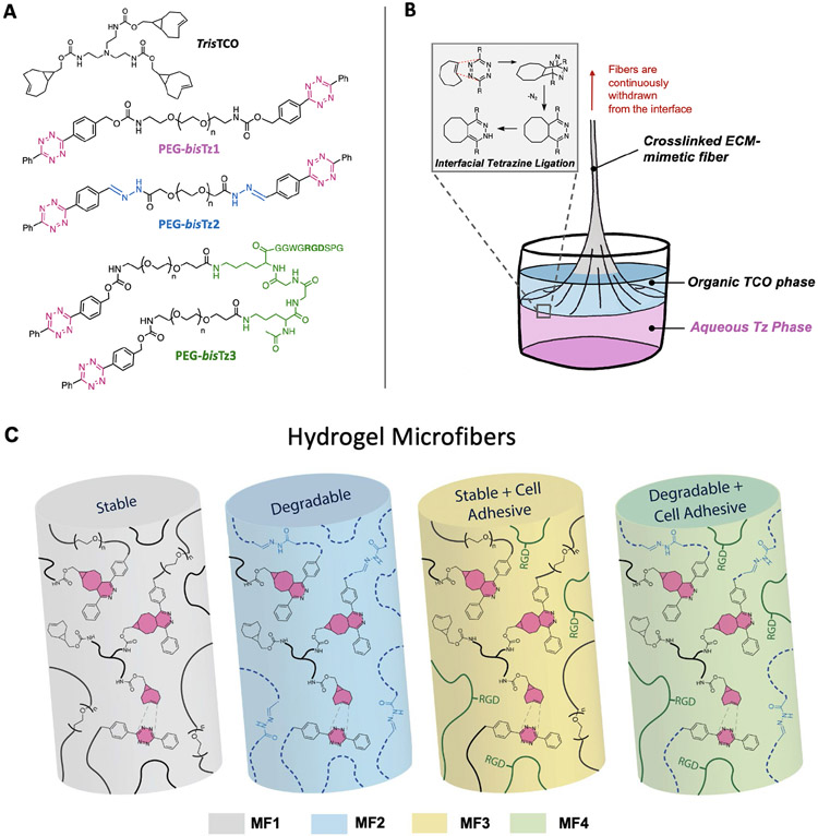
Crosslinked, degradable, and cell-adhesive hydrogel microfibers were synthesized via interfacial polymerization employing tetrazine ligation, an exceptionally fast bioorthogonal reaction between strained trans-cyclooctene (TCO) and s-tetrazine (Tz). A hydrophobic trisTCO crosslinker and homo-difunctional poly(ethylene glycol) (PEG)-based macromers with the tetrazine group conjugated to PEG via a stable carbamate (PEG-bisTz1) bond or a labile hydrazone (PEG-bisTz2) linkage were synthesized. After laying an ethyl acetate solution of trisTCO over an aqueous solution of bisTz macromers, mechanically robust microfibers were continuously pulled from the oil-water interface. The resultant microfibers exhibited comparable mechanical and thermal properties but different aqueous stability. Combining PEG-bisTz2 and PEG-bisTz3 with a dangling arginine-glycine-aspartic acid (RGD) peptide in the aqueous phase yielded degradable fibers that supported the attachment and growth of primary vocal fold fibroblasts. The degradable and cell-adhesive hydrogel microfibers are expected to find utility in a wide array of tissue engineering applications.


Figures

Figure 1.
Figure 1.
Synthesis of PEG-bisTz2.
Figure 2.
Figure 2.
Synthesis of PEG-bisTz2 was confirmed via 1H NMR (A) and analytical HPLC monitoring absorbance at 300 nm and 214 nm (B). Integrating PEG backbone peaks (i and j) relative to tetrazine phenyl peaks (a and e) confirmed tetrazine end group functionality of >97%.
Figure 3.
Figure 3.
Structures of PEG-based bisTz derivatives and the hydrophobic trisTCO molecule used to create crosslinked microfibers with desired properties are shown in (A). Interfacial tetrazine ligation occurs at the oil-water interface between TCO and Tz (B). Crosslinked polymer film can be continuously withdrawn to yield microfibers with biologically relevant properties (C).
Figure 4.
Figure 4.
Cy5-tetrazine was doped into the aqueous phase during fiber pulling to visualize the microfibers (MF2). Fibers can be constructed into biomimetic hierarchical structures including interwoven meshes by collecting fibers around wire frames (A) or fibrous tubes by coalescing fibers around a cylindrical collector (B, C).
Figure 5.
Figure 5.
Optical images (20×) of representative dry and hydrated MFs (A), and the corresponding diameter distributions (B, C). MF1 and MF2 fiber populations all followed gaussian distributions, and their respective curves are shown as dotted lines. Scale bar = 100 μm.
Figure 6.
Figure 6.
DSC thermograms for the PEG-bisTz1 and MF1 (A), and PEG-bisTz2 and MF2 (B) show sharp singular melting peaks. Curves represent the second heating cycle.
Figure 7.
Figure 7.
Front and side illustrations of the fiber tensile testing device (A). Each fiber tested was wrapped around a hook attached to a soft-calibrated cantilevered beam. Tensile testing of fibers yielded force displacement curves of MF1 and MF2s shown here (B). Fiber diameter measurements were used to convert force displacement data into stress-strain curves, from which modulus values (C) could be ascertained. ns: non-significant, p > 0.05; **: significantly different, p = 0.0015, unpaired, two-tailed t-test.
Figure 8.
Figure 8.
(A) Scheme showing microfiber degradation via hydrazone hydrolysis. (B-G) Optical images of MF1 (D, E) and MF2 (B, C, F, G) after 1-h incubation in HCl at pH = 1 (B-E) or pH = 7.4 (F, G).
Figure 9.
Figure 9.
Fiber meshes were soaked in PBS (pH = 7.4) or acetate buffer (pH=5) for 2 weeks, and fiber integrity was monitored by optical microscope. Scale bar = 275μm.
Figure 10.
Figure 10.
Live/Dead staining of cells on fibrous MF3 (A-C) and MF4 (D-F) scaffolds is shown for days 1, 4, and 7. Cells are spreading well and appear to align with fibers at day 7. 5× images show cell-encased fiber meshes at day 7 (G, H). Average fold change in cell number significantly increased for both MF3 and MF4 fibers at day 7 relative to their respective day 4 values (I, ***: p= 0.004, ****: p < 0.0001, unpaired, two-tailed t-test). Cells on both fiber varieties showed high viability for all timepoints tested (J, non-significant, p > 0.05, unpaired, two-tailed t-test).

References

    1. Lutolf MP; Hubbell JA, Synthetic biomaterials as instructive extracellular microenvironments for morphogenesis in tissue engineering. Nat. Biotechnol 2005, 23 (1), 47–55. - PubMed
    1. Wang N; Butler JP; Ingber DE, Mechanotransduction across the cell surface and through the cytoskeleton. Science 1993, 260 (5111), 1124–1127. - PubMed
    1. Daley WP; Peters SB; Larsen M, Extracellular matrix dynamics in development and regenerative medicine. J. Cell Sci 2008, 121 (Pt 3), 255–264. - PubMed
    1. Kleinman HK; Philp D; Hoffman MP, Role of the extracellular matrix in morphogenesis. Curr. Opin. Biotechnol 2003, 14 (5), 526–532. - PubMed
    1. Giancotti FG; Ruoslahti E, Integrin signaling. Science 1999, 285 (5430), 1028–32. - PubMed

Publication types