Review
. 2022 Jun 14;13(6):945.
doi: 10.3390/mi13060945.

Overview of the MEMS Pirani Sensors

Affiliations
Review

Overview of the MEMS Pirani Sensors

Shaohang Xu et al. Micromachines (Basel). .

Abstract

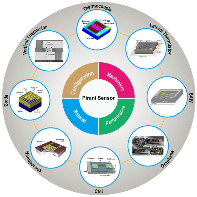
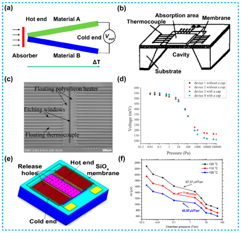
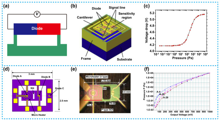
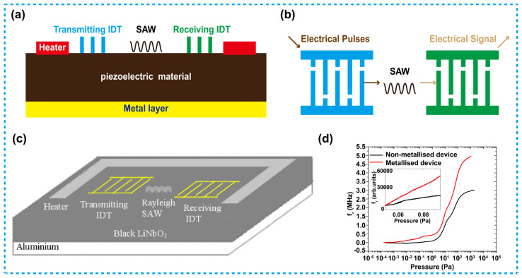
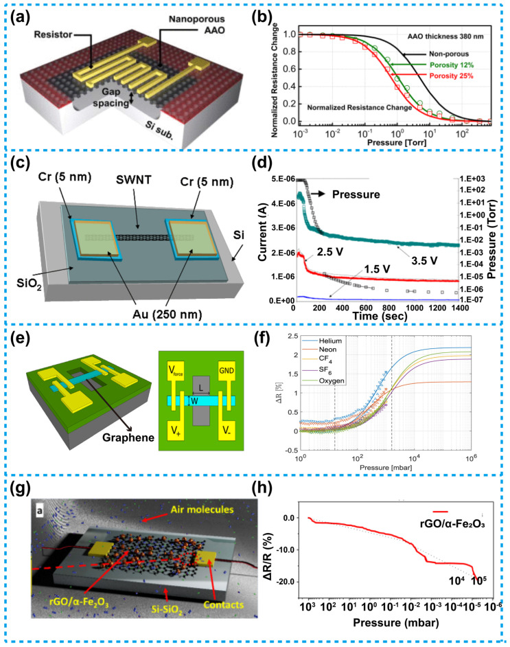
Vacuum equipment has a wide range of applications, and vacuum monitoring in such equipment is necessary in order to meet practical applications. Pirani sensors work by using the effect of air density on the heat conduction of the gas to cause temperature changes in sensitive structures, thus detecting the pressure in the surrounding environment and thus vacuum monitoring. In past decades, MEMS Pirani sensors have received considerable attention and practical applications because of their advances in simple structures, long service life, wide measurement range and high sensitivity. This review systematically summarizes and compares different types of MEMS Pirani sensors. The configuration, material, mechanism, and performance of different types of MEMS Pirani sensors are discussed, including the ones based on thermistors, thermocouples, diodes and surface acoustic wave. Further, the development status of novel Pirani sensors based on functional materials such as nanoporous materials, carbon nanotubes and graphene are investigated, and the possible future development directions for MEMS Pirani sensors are discussed. This review is with the purpose to focus on a generalized knowledge of MEMS Pirani sensors, thus inspiring the investigations on their practical applications.

Keywords: MEMS; Pirani sensors; functional materials; thermal conductivity; vacuum.


Conflict of interest statement

The authors declare no conflict of interest.

Figures

Figure 1
Figure 1
A summary about different types Pirani sensors.
Figure 2
Figure 2
Thermistor-based Pirani sensors with a vertical heat transfer configuration. (a) Schematic diagram of such a Pirani sensor. (b) A sensor using a NiCr microbridge, such a device has an extremely narrow gap between its heater and the heat sink [66]. (c) Heater power variation versus pressure for the sensor in (b), the device with a smaller gap between its heater and the heat sink has a larger sensitive range and higher sensitivity. (d) A Pirani sensor based on a dielectric membrane structure with four supporting beams [73]. (e) The output voltage versus pressure of the sensor in (d), its sensitive range was 10 to 105 Pa. (f) A Pirani sensor based on a dielectric membrane structure with six supporting beams [74]. (g) The output voltage versus pressure of the sensor in (f), its sensitive range was 10−1 to 105 Pa. (h) A dielectric membrane-based Pirani sensor with three different heater areas [72]. (i) The resistance variation versus pressure of the sensors in (h), the device with a larger heater area has higher sensitivity and a wider sensitive range than that with a smaller heater area.
Figure 3
Figure 3
A vertical heat transfer configuration thermistor-based Pirani sensor with a V-shaped groove. (a) Schematic diagram of the sensor. (b) The power per unit temperature versus pressure, the sensitive range of the device was 3 to 105 Pa [75].
Figure 4
Figure 4
Thermistor-based Pirani sensors using the lateral heat transfer configuration: (a) Typical schematics of such a sensor. (b) Structure diagram of such a sensor [78]. (c) Thermal impedance versus pressure of the sensor mentioned in (b), the sensitive range of the device was 1 to 1000 Pa. (d) SEM image of the DWP sensor. (e) SEM image of the SOG device [79]. (f) Thermal impedance versus pressure of the DWP and SOG sensors mentioned in (d,e), showing the different sensitive ranges of the two devices.
Figure 5
Figure 5
Thermocouple-based Pirani sensors. (a) A schematic diagram illustrating working principle of the Seebeck effect. (b) A schematic diagram of a conventional thermopile device. (c) Diagram of a thermocouple-based Pirani sensor with a heater located beside the hot ends [89]. (d) The output voltage versus gas pressure of the Pirani sensor mentioned in (c), the sensitive range of the device was 5 × 10⁻³ to 105 Pa. (e) Diagram of a thermopile used for constructing a thermocouple-based Pirani sensor [90]. (f) The output voltage versus gas pressure at different heating power of the Pirani sensor mentioned in (e), the sensitive range of the device was 10−1 to 104 Pa.
Figure 6
Figure 6
Diode-based Pirani sensors. (a) A schematic view of the diode-based Pirani sensors. (b) Schematic of a diode-based Pirani sensor based on a series of diodes [91]. (c) Voltage as a function of vacuum pressure; the sensitive range was 10−1 to 104 Pa. (d) Schematic and (e) Micrographs of a diode-based Pirani sensor with diode-thermistor group combined with a heater [92]. (f) Relationship between pressure and output voltage difference for the sensor in (e), the sensitive range of the device was 2 × 10⁻³ to 105 Pa.
Figure 7
Figure 7
SAW-based Pirani sensors. (a) Schematic of a SAW Pirani sensor. (b) Structure of the interdigital transducers. (c) Schematic diagram of a metallized SAW Pirani sensor [98]. (d) Frequency response as a function of pressure observed for the nonmetallized and metallized devices, the sensitivity of the metallized device is higher than that of the nonmetallized device.
Figure 8
Figure 8
A Pirani sensor based on functional materials. (a) Schematic of the nanoporous AAO-based Pirani sensor [99]. (b) Normalized resistance of the sensor versus pressure, with a 380 nm thick AAO membrane, the curve shifts to the left, indicating a better ability to detect low pressure. (c) Schematic of a Pirani sensor based on SWNT [100]. (d) Dynamic pressure response of device in (c), the sensitive range reaches 10−6 to 760 Torr (about 10−4 to 105 Pa). (e) Schematic of a sheet graphene-based Pirani sensor [103]. (f) Schematic diagram of resistance variation rate of the suspended graphene versus pressure in different gas circumstances. (g) Schematic and principle of Pirani sensors based on rGO-αFe2O3 [104]. (h) Resistance variation rate of the device versus pressure, the sensitive range was about 4 × 10⁻⁶ to 103 mBar (4 × 10⁻⁴ to 105 Pa, 1 mbar = 100 Pa).
Figure 9
Figure 9
MEMS Pirani sensors for monitoring wafer-level packaging [115]. (a) Schematic diagram of a differential Pirani sensor. (b) The magnified view of a differential Pirani sensor. (c) The normalized resistance changes versus pressure. (d) Pressures of a vacuum-sealed wafer before and after 96 h of wafer-level uHAST tests, and the red area mean poorly sealed. (e) The relationships between five bonding recipes with their final cavity pressures.

Similar articles

Cited by

References

    1. Redhead P.A. Vacuum science and technology: 1950–2003. J. Vac. Sci. Technol. A Vac. Surf. Films. 2003;21:S12–S14. doi: 10.1116/1.1599870. - DOI
    1. Stach T., Johnson M.C., Stevens S., Burghaus U. Adsorption and reaction kinetics of SO2 on graphene: An ultrahigh vacuum surface science study. J. Vac. Sci. Technol. A Vac. Surf. Films. 2021;39:042201. doi: 10.1116/6.0001055. - DOI
    1. Li X., Shi Z., Behrouznejad F., Hatamvand M., Zhang X., Wang Y., Liu F., Wang H., Liu K., Dong H., et al. Highly efficient flexible perovskite solar cells with vacuum-assisted low-temperature annealed SnO2 electron transport layer. J. Energy Chem. 2021;67:1–7. doi: 10.1016/j.jechem.2021.09.021. - DOI
    1. Belič I. Neural networks and modelling in vacuum science. Vacuum. 2006;80:1107–1122. doi: 10.1016/j.vacuum.2006.02.017. - DOI
    1. Lasek K., Li J., Kolekar S., Coelho P.M., Guo L., Zhang M., Wang Z., Batzill M. Synthesis and characterization of 2D transition metal dichalcogenides: Recent progress from a vacuum surface science perspective. Surf. Sci. Rep. 2021;76:100523. doi: 10.1016/j.surfrep.2021.100523. - DOI

LinkOut - more resources