Review
. 2022 Jun 18;13(6):968.
doi: 10.3390/mi13060968.

A Critical Review on the Sensing, Control, and Manipulation of Single Molecules on Optofluidic Devices

Affiliations
Review

A Critical Review on the Sensing, Control, and Manipulation of Single Molecules on Optofluidic Devices

Mahmudur Rahman et al. Micromachines (Basel). .

Abstract

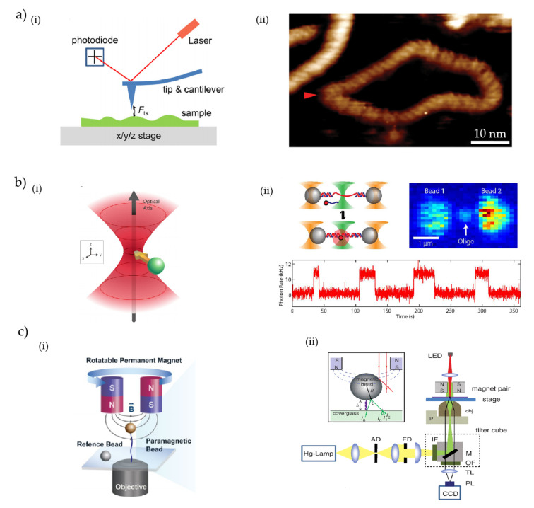
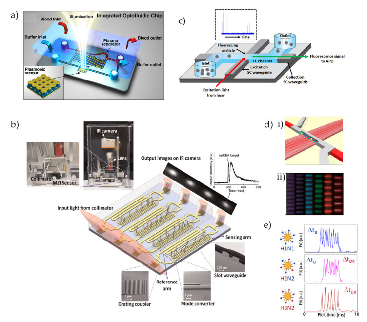
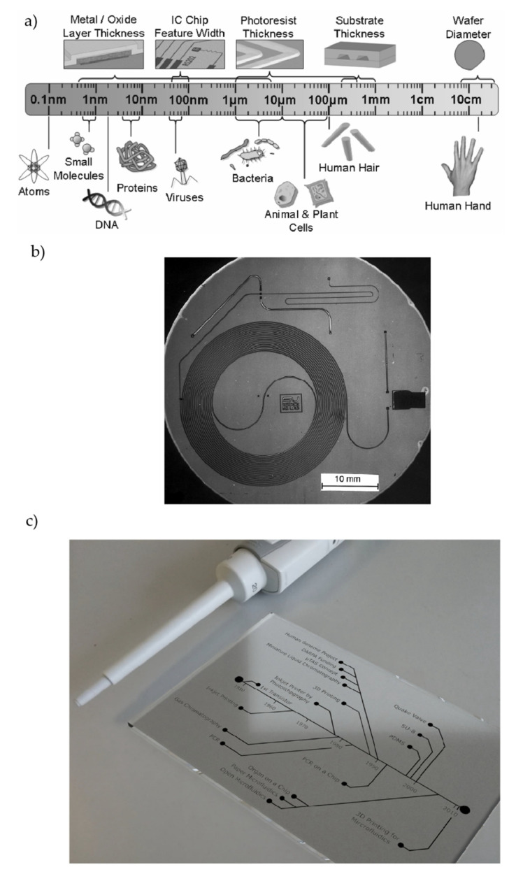
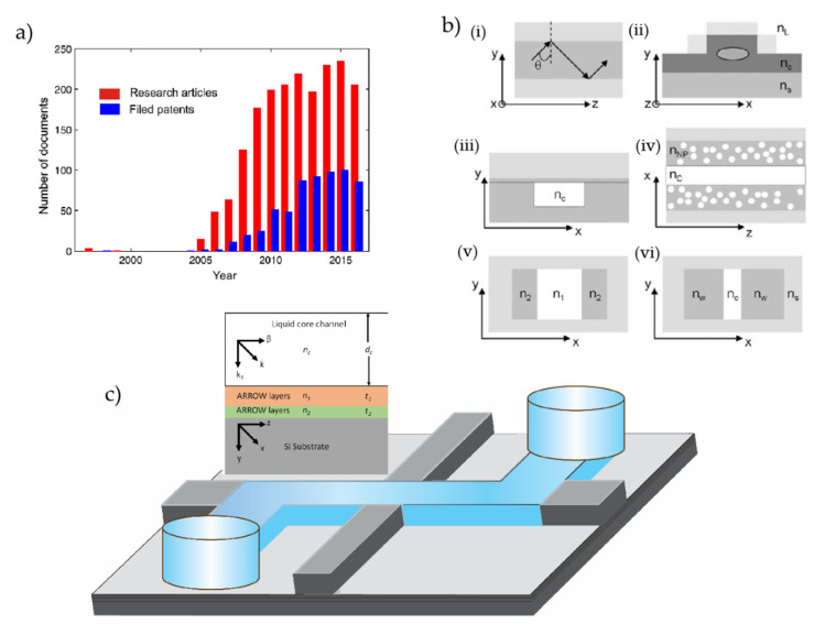
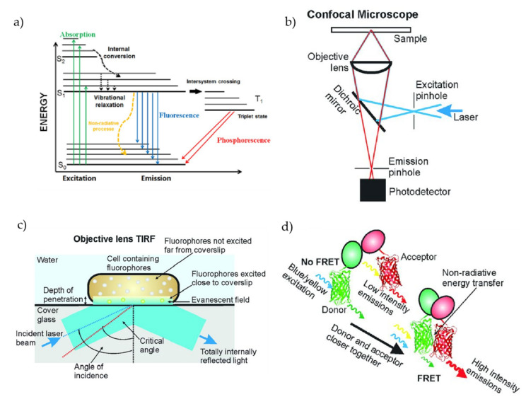
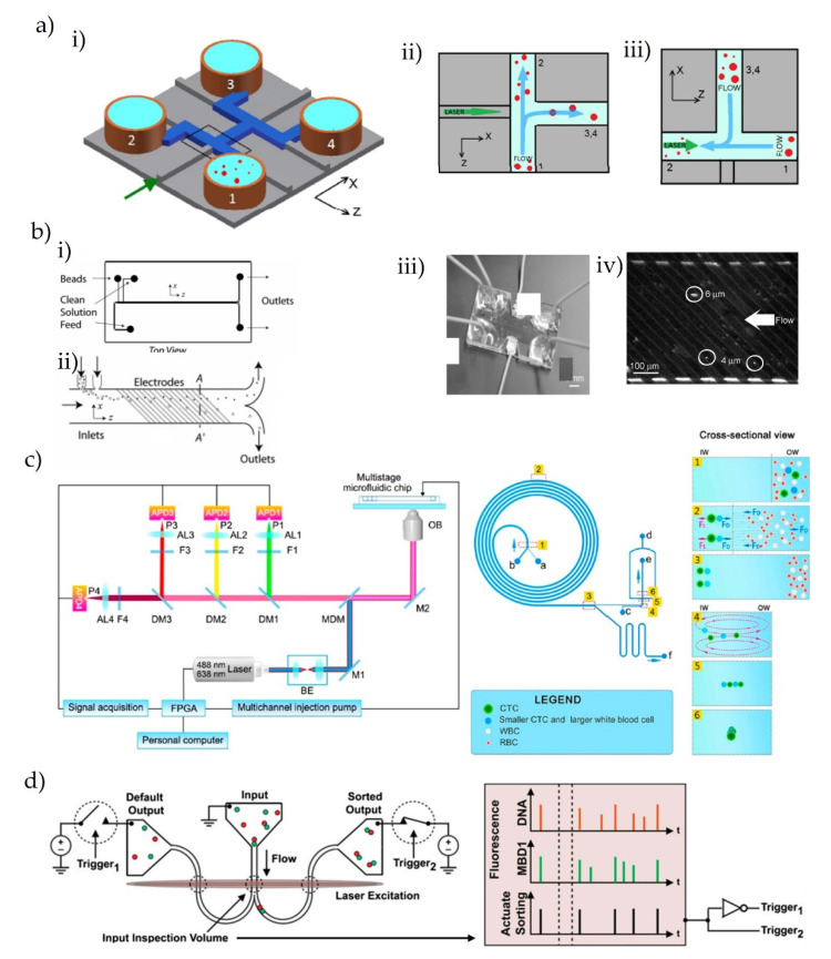
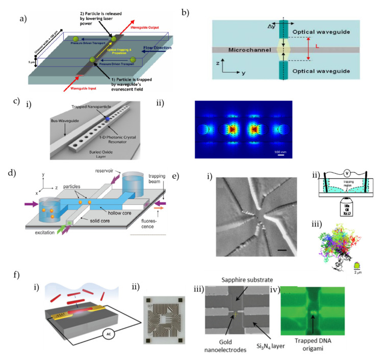
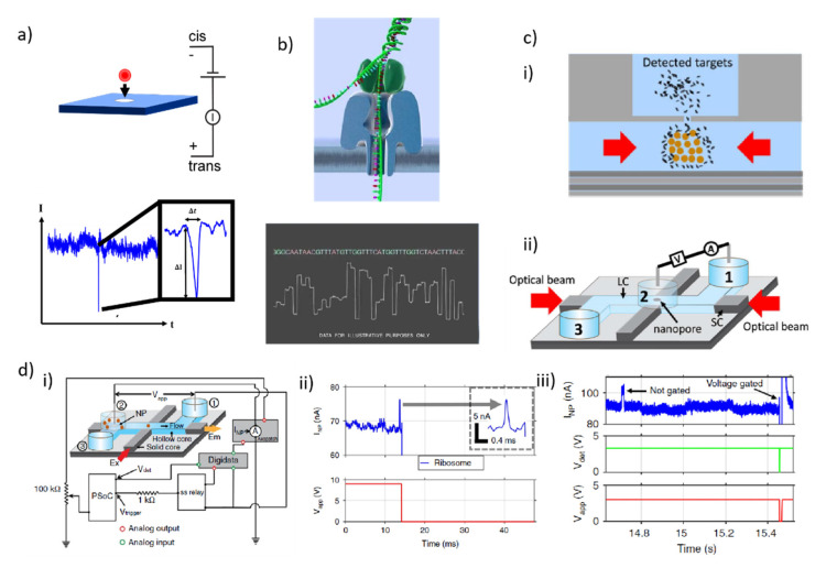
Single-molecule techniques have shifted the paradigm of biological measurements from ensemble measurements to probing individual molecules and propelled a rapid revolution in related fields. Compared to ensemble measurements of biomolecules, single-molecule techniques provide a breadth of information with a high spatial and temporal resolution at the molecular level. Usually, optical and electrical methods are two commonly employed methods for probing single molecules, and some platforms even offer the integration of these two methods such as optofluidics. The recent spark in technological advancement and the tremendous leap in fabrication techniques, microfluidics, and integrated optofluidics are paving the way toward low cost, chip-scale, portable, and point-of-care diagnostic and single-molecule analysis tools. This review provides the fundamentals and overview of commonly employed single-molecule methods including optical methods, electrical methods, force-based methods, combinatorial integrated methods, etc. In most single-molecule experiments, the ability to manipulate and exercise precise control over individual molecules plays a vital role, which sometimes defines the capabilities and limits of the operation. This review discusses different manipulation techniques including sorting and trapping individual particles. An insight into the control of single molecules is provided that mainly discusses the recent development of electrical control over single molecules. Overall, this review is designed to provide the fundamentals and recent advancements in different single-molecule techniques and their applications, with a special focus on the detection, manipulation, and control of single molecules on chip-scale devices.

Keywords: fluorescence; lab-on-a-chip; microfluidics; nanopore; optofluidics; single-molecule method.


Conflict of interest statement

The authors declare no conflict of interest.

Figures

Figure 3
Figure 3
(a) (i) Basic working principle of AFM. Schematic of typical AFM. The tip-sample force Fts induces a deflection of the cantilever, which is detected by recording the position of the reflected laser beam with a position-sensitive photodiode [150]. (ii) High-resolution AFM images of natively supercoiled DNA minicircles [159]. (b) (i) Schematic representation of the principle of optical tweezer [190]. (ii) Combined high-resolution optical tweezers and confocal microscope. Dual optical traps (outer cones) hold polystyrene microspheres (spheres) tethered by a DNA construct (here a DNA hairpin), while a confocal microscope (middle cone) detects fluorescence from a single molecule [199]. (c) (i) Illustration of the magnetic tweezers setup [211]. (ii) Experimental setup for biomolecular calibration based on DNA hairpin unfolding using magnetic tweezers [215].
Figure 5
Figure 5
(a) Integrated Dengue virus biosensor comprising an in-line microfluidic blood plasma separator and a cavity-coupled nanoimprinted plasmonic array. Inset corresponds to the nanoimprinted plasmonic biosensor composed of a gold mirror (80 nm), a dielectric film spacer (∼700 nm) embossed with a square array of holes, a conformal thin film of aluminum oxide layer (20 nm) as the fluid barrier, and a thin gold film (30 nm) [268]. (b) Schematic diagram of the MZI biosensor system for miRNA detection [269]. (c) Principle of fluorescence-based particle detection in ARROW optofluidic devices. Inset: an actual APD trace of particle detection (Figure 5c is used upon permission from the Applied Optics group at the University of California, Santa Cruz, CA, USA]. (d) (i) Schematic view of MMI waveguide intersecting with a fluidic microchannel containing target particles [276]. (ii) Photographs of multispot excitation patterns created in fluidic channel filled with fluorescent liquid. The entire visible spectrum is covered by independent channels (405 nm/11 spots, 453/10, 488/9, 553/8, 633/7, 745/6). (The original black and white color scale was rendered in the actual excitation colors) [276]. (e) Schematic view of the labeling scheme for the three influenza types and their resulting single-virus fluorescence signals; the H2N2 virus shows a mixture of six and nine peaks upon blue and dark red excitation [276].
Figure 1
Figure 1
(a) Approximate length scales for several biological and micro fabrication structures [50]. (b) Photograph of a gas chromatograph integrated on a planar silicon wafer fabricated by Terry and co-workers at Stanford University [59]. (c) Timeline highlighting the main advances in the field of microfluidics starting with the invention of the transistor and leading up to the rise in 3D-printed devices [62].
Figure 2
Figure 2
(a) The numbers of published research articles and filed patents in chronological order in the domain of optofuidics (data retrieved from Scopus on 26 May 2017) [119]. (b) Total internal reflection (TIR)-based waveguides [121]. (i) TIR principle in slab waveguide, (ii) cross section of solid core ridge waveguide with mode area (ellipse) and penetration area into surrounding liquid (hatched areas); (iii) liquid-core waveguide (LCW) cross section, (iv) nanoporous cladding waveguide (side view), (v) liquid–liquid core (L2) waveguide (cross section); (vi) slot waveguide (cross section). (c) Schematic representation of a typical ARROW optofluidic device with the wave vectors ((c) is used upon permission from the Applied Optics group at the University of California, Santa Cruz, CA, USA).
Figure 4
Figure 4
(a) Perrin Jablonski diagram of fuorescence and phosphorescence [232]. (b) Schematic representation of a confocal microscope [233]. (c) Schematic representation of TIRF showing the illumination of fluorophores close to the glass coverslip surface [233]. (d) Schematic representation of the FRET principle based on the non-radiative energy transfer which occurs when donor and acceptor dyes pair [233].
Figure 6
Figure 6
(a) (i) Layout of the ARROW optofluidic sorting device [283]. (ii,iii) Orientation of laser and flows [283]. (b) (i) Schematic of the sorting device with three inlets and two outlets [288] (ii) A cross-sectional view of the flow channel shows the locations of the planar electrodes and the beads during operation [288]. (iii) Photograph of the actual device [288]. (iv) Snapshot of 4- and 6-ím particles after separation at a distance of 30 mm from the inlet [288]. (c) Schematic Diagram of the Optical Path of the Four-Color Fluorescence Detection System and the Overall Composition of the OFCM. BE, Beam Expander Collimator; M1, M2, Reflectors; MDM, Multiband Dichroic Mirror; OB, Objective; DM1–DM3, Dichroic Mirrors; F1–F4, Filters; AL1–AL4, Lens; P1–P4, Pinholes; APD1–APD4, Avalanche Photodiodes; FPGA, Field-Programmable Gate Array [306]. (d) Single molecule detection and sorting [315].
Figure 7
Figure 7
(a) Schematic of trapping experiment. The optical waveguide propulsion is perpendicular to the direction of the pressure-driven flow in the channel [333]. (b) Basic scheme of the optofluidic chip: the two waveguides emit counter-propagating Gaussian beams. The sample under testing flows into the microchannel [334]. (c) (i) 3D schematic of the one-dimensional photonic crystal resonator optical trapping architecture [337] (ii) 3D FEM simulation illustrating the strong field confinement and amplification within the one-dimensional resonator cavity [337]. (d) Schematic layout of optofluidic loss-based trapping and manipulation of particles, showing intersecting solid- and liquid-core ARROW waveguides and relevant optical beam paths [279]. (e) (i) Glass microfluidic cell for the ABEL trap with the trapping region showing the patterned glass cell [338]. (ii) The microfluidic cell sits above the oil-immersion objective of an inverted optical microscope capable of observing single molecules [338]. (iii) Trajectories of 13 trapped particles of TMV [338]. (f) Dielectrophoretic chip for trapping DNA origami [341]. (i) Device schematic structure of a dielectrophoresis chip on a sapphire substrate. Generated AC electric field in between gold nanoelectrodes absorbs DNA origamis to the high-intensity region of the electric field and immobilizes it in a specific direction by binding the thiol linkers of DNA origami to gold electrodes; (ii) Optical image of a fabricated chip on a sapphire substrate including 14 devices; (iii) SEM image of a typical device on the chip showing gold nanoelectrodes and nitride encapsulation; and (iv) Fluorescent image of a device with DNA origamis trapped between nanoelectrodes.
Figure 8
Figure 8
(a) Schematic illustration of the nanopore working principle and detection signal [14]. (b) The principle of nanopore-based nucleic acid sequencing [389]. (c) Trap-assisted capture rate enhancement of a nanopore [422]. (i) A cartoon depicting the conceptual visualization of TACRE. (ii) Schematic illustration of the experimental setup. (d) On-demand target delivery on a programmable ARROW optofluidic device [275]. (i) Schematic illustration with feedback control mechanisms. (ii) Current (top) and voltage (bottom) trace of a voltage gated single ribosome delivery. (iii) Current (top), identification signal (middle), and voltage (bottom) trace of identification and voltage gating of only λ-DNAs from a mixture of λ-DNA and ribosome.

Similar articles

Cited by

References

    1. Miller H., Zhou Z., Shepherd J., Wollman A.J.M., Leake M.C. Single-Molecule Techniques in Biophysics: A Review of the Progress in Methods and Applications. Rep. Prog. Phys. 2018;81:024601. doi: 10.1088/1361-6633/aa8a02. - DOI - PubMed
    1. Xie X.S., Choi P.J., Li G.W., Nam K.L., Lia G. Single-Molecule Approach to Molecular Biology in Living Bacterial Cells. Annu. Rev. Biophys. 2008;37:417–444. doi: 10.1146/annurev.biophys.37.092607.174640. - DOI - PubMed
    1. Gilboa T., Garden P.M., Cohen L. Single-Molecule Analysis of Nucleic Acid Biomarkers—A Review. Anal. Chim. Acta. 2020;1115:61–85. doi: 10.1016/j.aca.2020.03.001. - DOI - PubMed
    1. Ha T. Single-Molecule Methods Leap Ahead. Nat. Methods. 2014;11:1015–1018. doi: 10.1038/nmeth.3107. - DOI - PubMed
    1. Ishijima A., Yanagida T. Single Molecule Nanobioscience. Trends Biochem. Sci. 2001;26:438–444. doi: 10.1016/S0968-0004(01)01860-6. - DOI - PubMed

LinkOut - more resources