Review
. 2022 Jun 14;27(12):3829.
doi: 10.3390/molecules27123829.

The Development of iDPC-STEM and Its Application in Electron Beam Sensitive Materials

Affiliations
Review

The Development of iDPC-STEM and Its Application in Electron Beam Sensitive Materials

Hongyi Wang et al. Molecules. .

Abstract

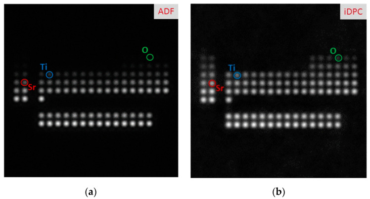
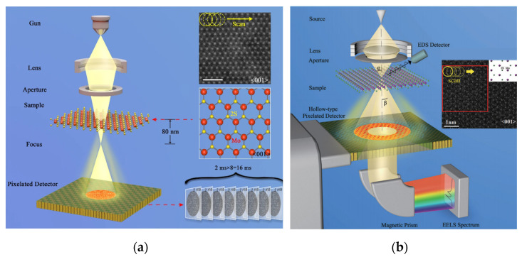
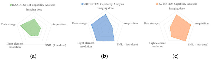
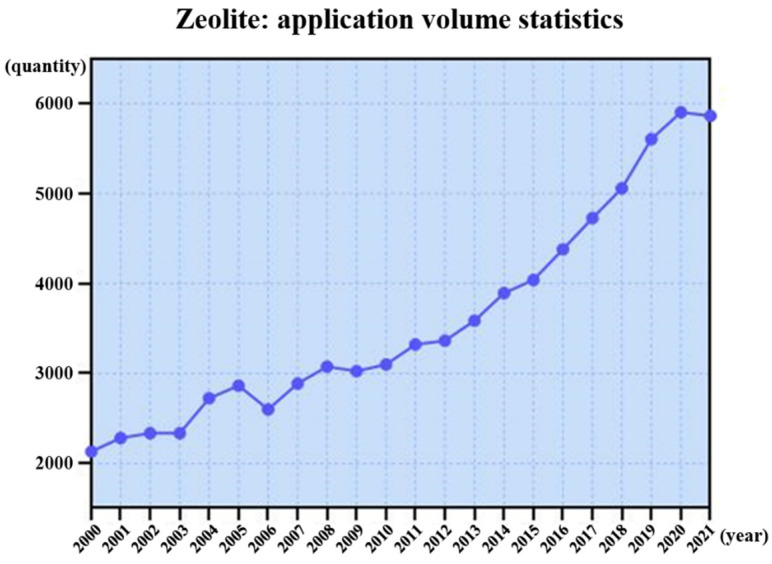
The main aspects of material research: material synthesis, material structure, and material properties, are interrelated. Acquiring atomic structure information of electron beam sensitive materials by electron microscope, such as porous zeolites, organic-inorganic hybrid perovskites, metal-organic frameworks, is an important and challenging task. The difficulties in characterization of the structures will inevitably limit the optimization of their synthesis methods and further improve their performance. The emergence of integrated differential phase contrast scanning transmission electron microscopy (iDPC-STEM), a STEM characterization technique capable of obtaining images with high signal-to-noise ratio under lower doses, has made great breakthroughs in the atomic structure characterization of these materials. This article reviews the developments and applications of iDPC-STEM in electron beam sensitive materials, and provides an outlook on its capabilities and development.

Keywords: electron beam sensitive materials; electron microscopic characterization; iDPC-STEM; low dose.


Conflict of interest statement

The authors declare no conflict of interest.

Figures

Figure 1
Figure 1
The history of microscope development: more comprehensive and more realistic structural information is the current mainstream development direction.
Figure 2
Figure 2
High-energy electron beams will inevitably introduce damage while reducing structural information: knock on damage, radiolysis damage, electrostatic charging, and heating.
Figure 3
Figure 3
Application status of iDPC-STEM in electron beam sensitive materials characterization.
Figure 4
Figure 4
The schematic diagram of technical principle: partition probe, electrostatic potential imaging, and integral.
Figure 5
Figure 5
The comparison of single-atom contrast in the range Z = 1–103 obtained by simulations: HAADF-STEM image (a) and iDPC-STEM image (b) Reprinted/adapted with permission from Ref. [24]. Copyright 2016, Cambridge University Press.
Figure 6
Figure 6
(a) Schematic diagram of the optical path of the 4D-STEM. Reprinted/adapted with permission from Ref. [55]. Copyright 2019, Springer Nature. (b) Based on the STEM mode, the ring-shaped electron detector is replaced by an arrayed detector, and the entire diffraction pattern is recorded at each scanning position Reprinted/adapted with permission from Ref. [56]. Copyright 2018, American Physical Society.
Figure 7
Figure 7
The capability comparison of HAADF-STEM (a), iDPC-STEM (b) and K2 camera (c).
Figure 8
Figure 8
The research quantity curve of zeolite in the past two decades.
Figure 9
Figure 9
(a) MTA schematic; (b) HAADF-STEM of the synthesized ZSM-5; (c) iDPC-STEM Reprinted/adapted with permission from Ref. [92]. Copyright 2011, Royal Society of Chemistry.
Figure 9
Figure 9
(a) MTA schematic; (b) HAADF-STEM of the synthesized ZSM-5; (c) iDPC-STEM Reprinted/adapted with permission from Ref. [92]. Copyright 2011, Royal Society of Chemistry.
Figure 10
Figure 10
(a) The iDPC-STEM image of ZSM-5 from the <105> direction; (bd) detailed analysis from (a); (e) the atomically flat (010) surface with clear Si-O dangling bonds. Reprinted/adapted with permission from Ref. [94]. Copyright 2019, Advanced Materials.
Figure 11
Figure 11
(a) The HAADF-STEM image of assembled ZSM-5 particles; (b,c) The iDPC-STEM images of the (010) interfaces in the areas marked in (a); (d,e) The zoom-in interface areas of iDPC-STEM images marked in (b,c); (f,g) The FFT patterns corresponding to (b) and (c), respectively. Reprinted/adapted with permission from Ref. [94]. Copyright 2019, Advanced Materials.
Figure 12
Figure 12
(a) iDPC-STEM image of Mo/ZSM-5; (b) Zoomed-in areas 1 (I), 2 (II), and 3 (III) of (a) with an atomic model. Reprinted/adapted with permission from Ref. [99]. Copyright 2019, Angewandte Chemie.
Figure 13
Figure 13
(a,b) iDPC-STEM image (b, top), the structural model (b, middle) and the simulated image (b, bottom); (c) shows the corresponding intensity profile acquired from the red-framed region in (a).Reprinted/adapted with permission from Ref. [102]. Copyright 2021, Springer Nature.
Figure 14
Figure 14
(ad) Magnified iDPC-STEM images with red box and intensity profiles (for red box) of SAPO-18 (a,c) and SAPO-34 (b,d)with blue box; (e) iDPC-STEM image of highly mixed SAPO-34 and SAPO-18 lattices inside; (f,g) iDPC-STEM images show the stacking sequences. Reprinted/adapted with permission from Ref. [109]. Copyright 2021, Applied Physics Letters.
Figure 15
Figure 15
The research quantity curve of MOF in the past two decades.
Figure 16
Figure 16
A series of electron microscopy images of MIL-101 acquired in different years: (a) HRTEM image in 2005. Reprinted/adapted with permission from Ref. [112]. Copyright 2005, American Chemical Society. (b) ADF-STEM image in 2016. Reprinted/adapted with permission from Ref. [113]. Copyright 2016, John Wiley and Sons. (c) low-dose HRTEM image (with DDEC) in 2019.(FFT for the white box) Reprinted/adapted with permission from Ref. [114]. Copyright 2019, American Chemical Society. (d) iDPC-STEM image in 2020. Reprinted/adapted with permission from Ref. [115]. Copyright 2020, Springer Nature.
Figure 16
Figure 16
A series of electron microscopy images of MIL-101 acquired in different years: (a) HRTEM image in 2005. Reprinted/adapted with permission from Ref. [112]. Copyright 2005, American Chemical Society. (b) ADF-STEM image in 2016. Reprinted/adapted with permission from Ref. [113]. Copyright 2016, John Wiley and Sons. (c) low-dose HRTEM image (with DDEC) in 2019.(FFT for the white box) Reprinted/adapted with permission from Ref. [114]. Copyright 2019, American Chemical Society. (d) iDPC-STEM image in 2020. Reprinted/adapted with permission from Ref. [115]. Copyright 2020, Springer Nature.
Figure 17
Figure 17
A series of electron microscopy images of the different surfaces in MIL-101: (a) The boundary includes most of the cage structure; (b) The boundary includes the whole of the cage structure; (c) The boundary includes few of the cage structure. And (i) HRETM; (ii) simulated image; (iii) structure model; (iv) iDPC-STEM. Reprinted/adapted with permission from Ref. [114]. Copyright 2019, American Chemical Society.
Figure 18
Figure 18
(a) a series of iDPC-STEM images with the increased cumulative electron beam doses; (bd) iDPC-STEM under different dose; (e,f) iDPC-STEM images before and after irradiation; (g,h) the corresponding FFT. Reprinted/adapted with permission from Ref. [116]. Copyright 2020, American Chemical Society.
Figure 19
Figure 19
(ac) A series of iDPC-STEM images with increased loading (TiO2); (df) Increased loading (TiO2) corresponding FFT. Red and blue outlines are overlaid on the images to highlight the positions of TiO2 units in separate types of mesopores. Scale bars: 5 nm. Reprinted/adapted with permission from Ref. [117]. Copyright 2020, Springer Nature.
Figure 19
Figure 19
(ac) A series of iDPC-STEM images with increased loading (TiO2); (df) Increased loading (TiO2) corresponding FFT. Red and blue outlines are overlaid on the images to highlight the positions of TiO2 units in separate types of mesopores. Scale bars: 5 nm. Reprinted/adapted with permission from Ref. [117]. Copyright 2020, Springer Nature.
Figure 20
Figure 20
The research quantity of perovskites in the past two decades.
Figure 21
Figure 21
(a) iDPC-STEM image of the LSMO layer in the virgin state; (b) is the enlarged image of the green box in (a). Reprinted/adapted with permission from Ref. [118]. Copyright 2021, AIP Publishing.
Figure 22
Figure 22
(a) HAADFSTEM images of selected areas; (b) corresponding iDPC-STEM images. The white box is to highlight and magnify the structure. Reprinted/adapted with permission from Ref. [119]. Copyright 2021, Springer Nature.

Similar articles

Cited by

References

    1. Adams C.J., Haddow M.F., Lusi M., Orpen A.G. Crystal engineering of lattice metrics of perhalometallate salts and MOFs. Proc. Natl. Acad. Sci. USA. 2010;107:16033–16038. doi: 10.1073/pnas.0910146107. - DOI - PMC - PubMed
    1. Feyand M., Mugnaioli E., Vermoortele F., Bueken B., Dieterich J.M., Reimer T., Kolb U., De Vos D., Stock N. Automated Diffraction Tomography for the Structure Elucidation of Twinned, Sub-micrometer Crystals of a Highly Porous, Catalytically Active Bismuth Metal-Organic Framework. Angew. Chem. Int. Ed. 2012;51:10373–10376. doi: 10.1002/anie.201204963. - DOI - PubMed
    1. Wu H., Chua Y.S., Krungleviciute V., Tyagi M., Chen P., Yildirim T., Zhou W. Unusual and Highly Tunable Missing-Linker Defects in Zirconium Metal–Organic Framework UiO-66 and Their Important Effects on Gas Adsorption. J. Am. Chem. Soc. 2013;135:10525–10532. doi: 10.1021/ja404514r. - DOI - PubMed
    1. Yakovenko A.A., Reibenspies J.H., Bhuvanesh N., Zhou H.C. Generation and applications of structure envelopes for porous metal–Organic frameworks. J. Appl. Crystallogr. 2013;46:346–353. doi: 10.1107/S0021889812050935. - DOI
    1. Song Q., Nataraj S.K., Roussenova M.V., Tan J.C., Hughes D.J., Li W., Sivaniah E. Zeolitic imidazolate framework (ZIF-8) based polymer nanocomposite membranes for gas separation. Energy Environ. Sci. 2012;5:8359–8369. doi: 10.1039/c2ee21996d. - DOI

MeSH terms

LinkOut - more resources