. 2022 Jul 4;13(1):3846.
doi: 10.1038/s41467-022-31429-7.

Design principles for water dissociation catalysts in high-performance bipolar membranes

Affiliations

Design principles for water dissociation catalysts in high-performance bipolar membranes

Lihaokun Chen et al. Nat Commun. .

Abstract

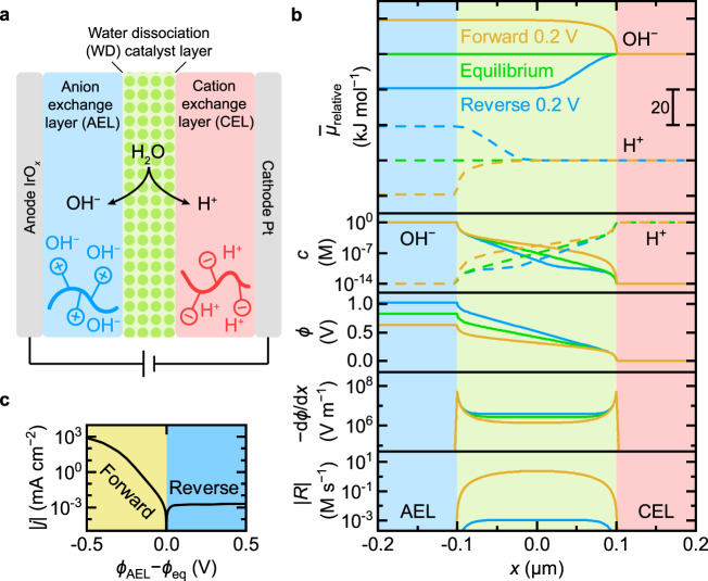
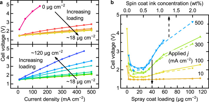
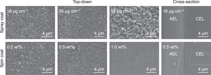
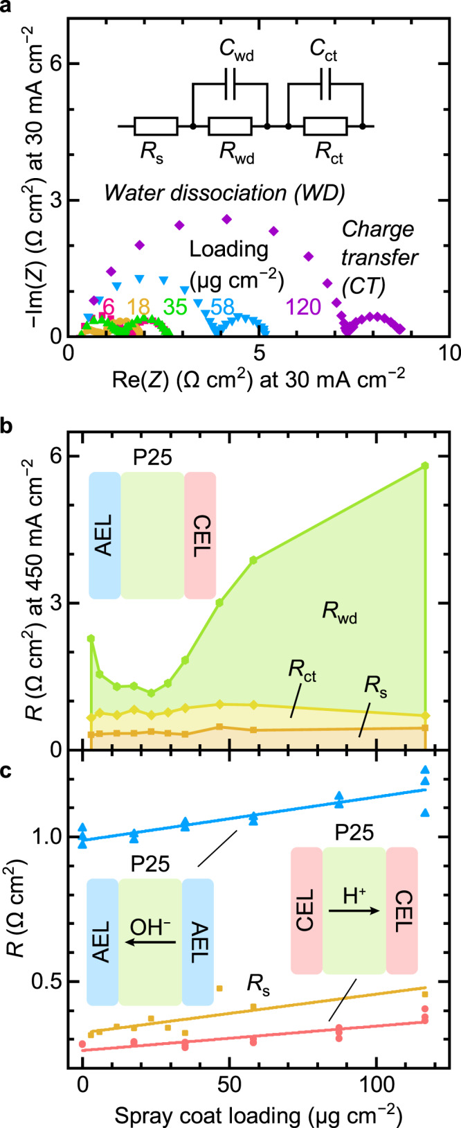
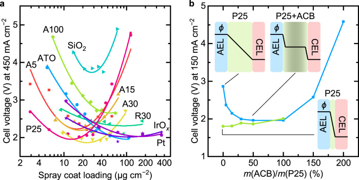
Water dissociation (WD, H2O → H+ + OH-) is the core process in bipolar membranes (BPMs) that limits energy efficiency. Both electric-field and catalytic effects have been invoked to describe WD, but the interplay of the two and the underlying design principles for WD catalysts remain unclear. Using precise layers of metal-oxide nanoparticles, membrane-electrolyzer platforms, materials characterization, and impedance analysis, we illustrate the role of electronic conductivity in modulating the performance of WD catalysts in the BPM junction through screening and focusing the interfacial electric field and thus electrochemical potential gradients. In contrast, the ionic conductivity of the same layer is not a significant factor in limiting performance. BPM water electrolyzers, optimized via these findings, use ~30-nm-diameter anatase TiO2 as an earth-abundant WD catalyst, and generate O2 and H2 at 500 mA cm-2 with a record-low total cell voltage below 2 V. These advanced BPMs might accelerate deployment of new electrodialysis, carbon-capture, and carbon-utilization technology.


Conflict of interest statement

The authors declare no competing interests.

Figures

Fig. 1
Fig. 1. Properties of BPMs.
a Schematic of a BPM electrolyzer. Pure water is fed through the anode and cathode gas-diffusion layers (GDLs) and diffuses into the AEL|CEL junction where water is dissociated with the aid of WD catalysts. b Steady-state numerical simulation results of a BPM at equilibrium (green), in forward bias 0.2 V (orange), and in reverse bias 0.2 V (blue). From top to bottom are the profiles of relative electrochemical potential μ¯relative, molar concentration c, electric potential ϕ, electric field dϕ/dx, and magnitude of the net reaction rate R (sum of dissociation and recombination). At equilibrium, the electrochemical potentials of each mobile species are the same across the whole BPM. c Simulated polarization curve of a BPM in forward bias and reverse bias. See Methods for more information.
Fig. 2
Fig. 2. Performance of BPM electrolyzers with TiO2-P25 as WD catalysts.
a Polarization curves of BPM electrolyzers with different loadings of TiO2-P25 WD catalyst deposited by spray coating. b Cell voltage of BPM electrolyzers as a function of spray-coating loading (solid lines) of TiO2-P25 and spin-coating ink concentration (dashed lines) of TiO2-P25 at different applied current densities. The 2.0 wt% sample is 1.0 wt% ink spun twice. The temperature is 55 ± 2 °C (maximum fluctuation).
Fig. 3
Fig. 3. SEM images of TiO2-P25 on the CEL and BPM cross-sections.
For spray-coated samples, the approximate loadings are given while for spin-coated samples, the ink concentrations are given. The optimal spin-coated WD catalysts layers are smoother, with more-uniform coverage, but only marginally improved performance.
Fig. 4
Fig. 4. Steady-state numerical simulated results of BPMs with different junction thickness and WD rate constant.
a Current density at reverse bias of 0.2 V as a function of junction thickness for different WD rate constants in the junction. b Polarization curves in reverse bias for different junction thickness with WD rate constant kf = 100 s−1. Similar results using the reported diffusion coefficients for H+ an OH along with the fixed ion concentration in the membranes estimated based on the manufacturer specifications are in Supplementary Fig. 4. See Methods for more information.
Fig. 5
Fig. 5. Impedance analysis of BPM electrolyzers.
a Nyquist plots of BPM electrolyzers at 30 mA cm−2 with different loadings of TiO2-P25 deposited by spray coating WD catalysts. The high frequency semicircle is assigned to WD, while the low frequency one to charge transfer. The inset shows the equivalent circuit used to fit the EIS data. b Extracted resistance values at 450 mA cm−2 as a function of TiO2-P25 loading. c Comparison of series resistance Rs (orange) extracted from BPM electrolyzer EIS data at 450 mA cm−2 with the resistance of PEM (red) and AEM (blue) electrolyzers at 300–500 mA cm−2 as a function of TiO2-P25 loading.
Fig. 6
Fig. 6. Performance of BPM electrolyzers with various WD catalysts.
a Cell voltage of BPM electrolyzers as a function of spray-coated loading of various WD catalysts at 450 mA cm−2. Lines are added to serve as a guide for the eye. For various TiO2, A = anatase and R = rutile. The number denotes the size of the nanoparticles (nm) provided by the manufacture. ATO = Sb:SnO2. b Cell voltage of BPM electrolyzers as a function of the mass ratio of acetylene carbon black (ACB) and TiO2-P25 at 150 mA cm−2. The blue line is for a thick layer of ∼120 μg cm−2 (∼2.4 μm) TiO2-P25, and the green line is for a thin layer of TiO2-P25 at optimal loading ∼18 μg cm−2 (∼360 nm). Only one of each type of device was fabricated for the data in this figure to illustrate trends, except for TiO2-P25. The error was estimated to be less than 5% (one standard deviation) based on seven devices fabricated with the best loading of TiO2-P25 catalysts (Supplementary Fig. S3). Insets are schematic proposed electric-potential profiles across the BPM junction.

References

    1. Giesbrecht PK, Freund MS. Recent advances in bipolar membrane design and applications. Chem. Mater. 2020;32:8060–8090. doi: 10.1021/acs.chemmater.0c02829. - DOI
    1. Pärnamäe R, et al. Bipolar membranes: a review on principles, latest developments, and applications. J. Membr. Sci. 2021;617:118538. doi: 10.1016/j.memsci.2020.118538. - DOI
    1. Fuller CS. Some analogies between semiconductors and electrolyte solutions. Rec. Chem. Prog. 1956;17:75–93.
    1. Frilette VJ. Preparation and characterization of bipolar ion exchange membranes. J. Phys. Chem. 1956;60:435–439. doi: 10.1021/j150538a013. - DOI
    1. Lovrecek B, Despic A, Bockris JOM. Electrolytic junctions with rectifying properties. J. Phys. Chem. 1959;63:750–751. doi: 10.1021/j150575a030. - DOI