. 2022 Jun 22;15(13):4421.
doi: 10.3390/ma15134421.

Finite Element Analysis of Steel Plates with Rectangular Openings Subjected to Axial Stress

Affiliations

Finite Element Analysis of Steel Plates with Rectangular Openings Subjected to Axial Stress

Ahmad Mahamad Al-Yacouby et al. Materials (Basel). .

Abstract

Steel plates with openings are among the important ship structural components used in the ship's hull to withstand the hydrostatic forces of the ocean, which cause sagging and hogging moments at the ship's bottom. The existence of openings on plates can cause structural rupture, stress concentration and a decrease in ultimate strength. This research is aimed at investigating the influence of selected parameters on the ultimate capacity of steel plates with rectangular holes subjected to axial stress, using ANSYS finite element analysis (FEA) under its non-linear static structural programme. The main parameters investigated in this paper are the plate thickness, opening aspect ratio, number of openings, position of openings, and the boundary condition of the plate. The influence of these parameters on the stress of plates and their deformation was evaluated. The comparison of the numerical simulation with the well-established analytical method using the Navier solution and Roark's Formulas showed a good agreement.

Keywords: finite element analysis; rectangular openings; steel plates; stress analysis.


Conflict of interest statement

The authors declare no conflict of interest, and the funders had no role in the design of the study; in the collection, analyses, or interpretation of data; in the writing of the manuscript; or in the decision to publish the results.

Figures

Figure 1
Figure 1
Plate floor details used in shipbuilding industry: (a) Flanges, (b) Traverse plate floor, (c) Cardboard strake.
Figure 2
Figure 2
Visual schematics of the modelled specimens. (a) S1; (b) S2, S3, S4, S5 & S6; (c) S7; (d) S8; (e) S9; (f) S10; (g) S11; (h) S12; (i) S13; (j) S14; (k) S15; (l) S16; (m) S17; (n) S18; (o) S19; (p) S20.
Figure 3
Figure 3
Boundary conditions of numerical models. (a) Plate with fixed boundary conditions; (b) plate with simply supported boundary conditions; (c) coordinate system of plates (x,y,z).
Figure 4
Figure 4
Plate maximum stress comparison between ANSYS FEA, Roark’s stress and Navier solution.
Figure 5
Figure 5
Plate maximum displacement comparison between ANSYS FEA, Roark’s Stress and Navier solution.
Figure 6
Figure 6
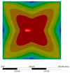
Stress contour for the unperforated steel plate.
Figure 7
Figure 7
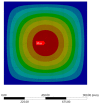
Displacement contour for the unperforated steel plate.
Figure 8
Figure 8
Influence of plate thickness on the plate maximum stress.
Figure 9
Figure 9
Influence of plate thickness on plate maximum displacement.
Figure 10
Figure 10
Variation in maximum stress of steel plate specimens with varied plate thickness over time.
Figure 11
Figure 11
Stress distribution contours for individual steel plate specimens with varied wall thickness.
Figure 12
Figure 12
Influence of plate opening aspect ratio on maximum stress.
Figure 13
Figure 13
Influence of plate opening aspect ratio on maximum displacement.
Figure 14
Figure 14
Variation in maximum stress of steel plate specimens with varying opening aspect ratios over time.
Figure 15
Figure 15
Stress distribution contours for individual steel plates with varying opening aspect ratios.
Figure 16
Figure 16
Influence of plate opening numbers on maximum stress.
Figure 17
Figure 17
Influence of opening numbers on the maximum displacement of plates.
Figure 18
Figure 18
Graph plot of the maximum stress of steel plate specimens with different plate opening numbers over time.
Figure 19
Figure 19
Stress distribution contours for individual steel plates with different plate opening numbers.
Figure 20
Figure 20
Influence of plate opening positions on plate maximum stress.
Figure 21
Figure 21
Influence of plate opening positions on plate maximum displacement.
Figure 22
Figure 22
Variation in maximum stress of steel plate specimens with differing plate opening positions.
Figure 23
Figure 23
Stress contour areas for individual steel plate specimens with differing plate opening positions.
Figure 24
Figure 24
Variation in plate maximum stress with different boundary conditions.
Figure 25
Figure 25
Variation in maximum displacement with different boundary conditions.
Figure 26
Figure 26
Stress distribution for individual plate specimens with different boundary conditions.

References

    1. Doan V.T., Liu B., Garbatov Y., Wu W., Guedes Soares C. Strength assessment of aluminium and steel stiffened panels with openings on longitudinal girders. Ocean. Eng. 2020;200:107047. doi: 10.1016/j.oceaneng.2020.107047. - DOI
    1. Yao T., Fujikubo M. Buckling and Ultimate Strength of Ship and Ship-Like Floating Structures. Butterworth-Heinemann; Oxford, UK: 2016.
    1. Laursen W. IACS Acts on MOL Comfort Report. 2015. [(accessed on 21 May 2022)]. Available online: https://www.maritime-executive.com/article/iacs-acts-on-mol-comfort-report.
    1. Paik J.K., Thayamballi A.K., Pedersen P.T., Park Y.I. Ultimate strength of ship hulls under torsion. Ocean Eng. 2001;28:1097–1133. doi: 10.1016/S0029-8018(01)00015-4. - DOI
    1. Molland A.F. The Maritime Engineering Reference Book: A Guide to Ship Design, Construction and Operation. Elsevier; Amsterdam, The Netherlands: 2011.

LinkOut - more resources