Review
. 2022 Jun 23;22(13):4735.
doi: 10.3390/s22134735.

Miniaturization of Laser Doppler Vibrometers-A Review

Affiliations
Review

Miniaturization of Laser Doppler Vibrometers-A Review

Yanlu Li et al. Sensors (Basel). .

Abstract

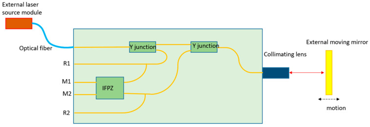
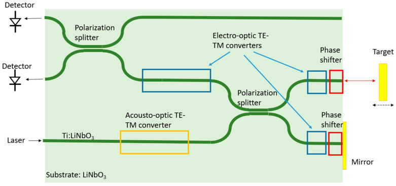
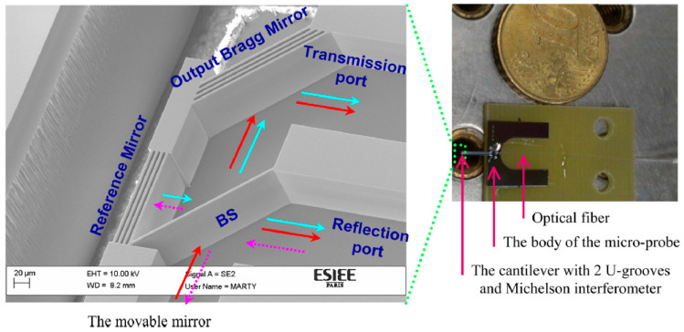
Laser Doppler vibrometry (LDV) is a non-contact vibration measurement technique based on the Doppler effect of the reflected laser beam. Thanks to its feature of high resolution and flexibility, LDV has been used in many different fields today. The miniaturization of the LDV systems is one important development direction for the current LDV systems that can enable many new applications. In this paper, we will review the state-of-the-art method on LDV miniaturization. Systems based on three miniaturization techniques will be discussed: photonic integrated circuit (PIC), self-mixing, and micro-electrochemical systems (MEMS). We will explain the basics of these techniques and summarize the reported miniaturized LDV systems. The advantages and disadvantages of these techniques will also be compared and discussed.

Keywords: laser Doppler vibrometry; miniaturization; photonic integrated circuit.


Conflict of interest statement

The authors declare no conflict of interest.

Figures

Figure 1
Figure 1
Schematic diagram of laser Doppler sensors using external interference (a) and internal interference (b). The external interference is usually used in laser Doppler velocimetry and the internal interference is usually used in laser Doppler vibrometry.
Figure 2
Figure 2
Schematic diagram of (a) homodyne interferometer and (b) heterodyne interferometer. A beam splitter (BS) creates the reference and measurement arms of the interferometer. The heterodyne interferometer has an optical frequency shifter (OFS) in the reference arm. One can also use polarization beam splitters and quarter-wave plates in the LDV system to improve the coupling efficiency of reflection and the isolation of the laser source. However, they are not mentioned in the plotted system in this figure to simplify the schematic of the system.
Figure 3
Figure 3
The two parts of the LDV sensor head.
Figure 4
Figure 4
The schematic of the LDV design based on a silica PIC.
Figure 5
Figure 5
Schematic of integrated interferometers demonstrated on GaAs/AlGaAs. (a) A single Michelson interferometer and (b) a double Michelson interferometer.
Figure 6
Figure 6
Schematic of the homodyne LDV design with an external laser source and PDs. This is a redraw of the system shown in Ref. [34].
Figure 7
Figure 7
The microscopic image of a six-beam homodyne LDV.
Figure 8
Figure 8
Schematic of an SOI-based vibrometer measuring a cantilever on top of the sensor grating.
Figure 9
Figure 9
Schematic of the integrated optical heterodyne interferometer in Ref. [46].
Figure 10
Figure 10
Schematic diagram of a single-sideband suppressed-carrier (SSB-SC) modulator to generate an optical frequency shift used for PIC-based heterodyne LDV systems.
Figure 11
Figure 11
Schematic diagram of an optical frequency shifter based on the switch-serrodyne method.
Figure 12
Figure 12
A typical configuration of a self-mixing LDV.
Figure 13
Figure 13
The five different regimes of laser feedback. Adapted from Refs. [129,130].
Figure 14
Figure 14
A schematic configuration of a self-mixing heterodyne LDV.
Figure 15
Figure 15
Photograph of the micro-machined optical interferometer micro-probe together with SEM photography zooming on the Michelson interferometer integrated at its end. The different elements are described along with the transmission and the reflection ports. Magenta arrows designate the injected light, red arrows designate the path of the light beam reflected from the movable mirror (the movable mirror is not present in this figure), and cyan arrows designate the path of the light beam reflected from the reference mirror. Reprinted with permission from Ref. [146].

References

    1. Doppler C. Abhandlungen der königlichen Böhm. Gesellschaft der Wissenschaften. Volume 2. Verlag der Königl. Böhm. Gesellschaft der Wissenschaften; Prague, Czech Republic: 1842. Ueber das farbige Licht der Doppelsterne und einiger anderer Gestirne des Himmels; pp. 465–482.
    1. Yeh Y., Cummings H. Localized fluid flow measurements with a HeNe laser spectrometer. Appl. Phys. Lett. 1964;4:176–178. doi: 10.1063/1.1753925. - DOI
    1. Tropea C. Laser Doppler anemometry: Recent developments and future challenges. Meas. Sci. Technol. 1995;6:605–619. doi: 10.1088/0957-0233/6/6/001. - DOI
    1. Rajan V., Varghese B., van Leeuwen T., Steenbergen W. Review of methodological developments in laser Doppler flowmetry. Lasers Med. Sci. 2009;24:269–283. doi: 10.1007/s10103-007-0524-0. - DOI - PubMed
    1. Rothberg S., Allen M., Castellini P., Maio D.D., Dirckx J., Ewins D., Halkon B., Muyshondt P., Paone N., Ryan T., et al. An international review of laser Doppler vibrometry: Making light work of vibration measurement. Opt. Lasers Eng. 2019;99:11–22. doi: 10.1016/j.optlaseng.2016.10.023. - DOI

LinkOut - more resources