. 2022 Jun 25;22(13):4818.
doi: 10.3390/s22134818.

Physics of Composites for Low-Frequency Magnetoelectric Devices

Affiliations

Physics of Composites for Low-Frequency Magnetoelectric Devices

Mirza Bichurin et al. Sensors (Basel). .

Abstract

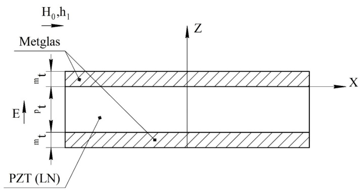
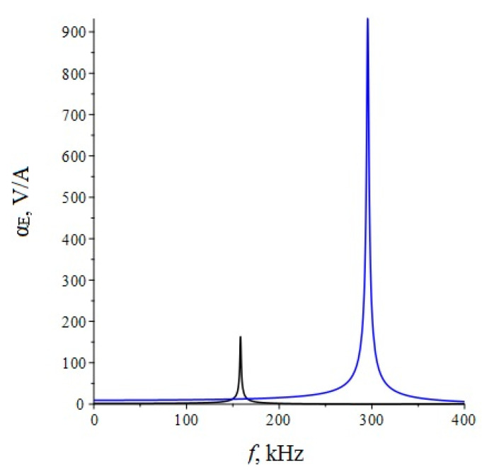
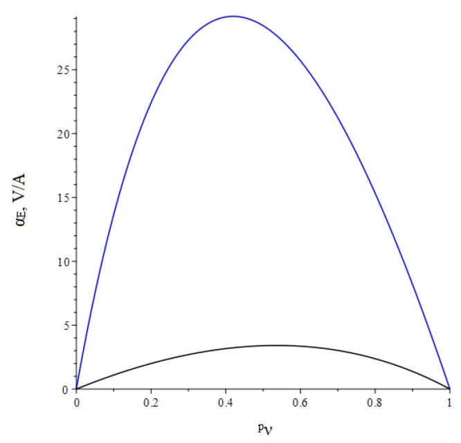
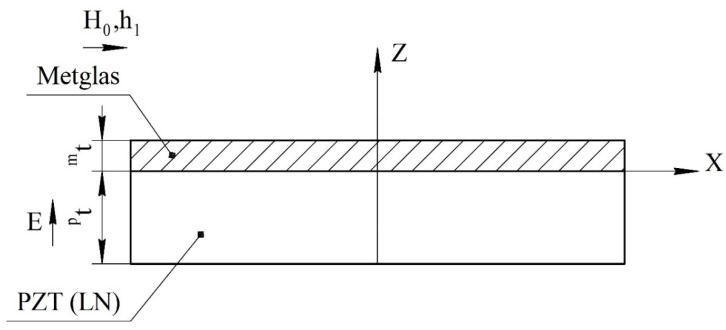
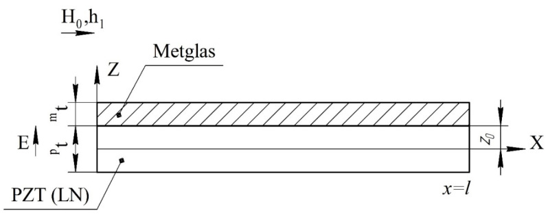
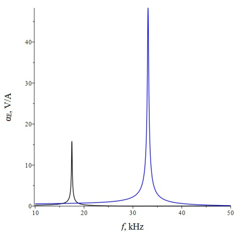
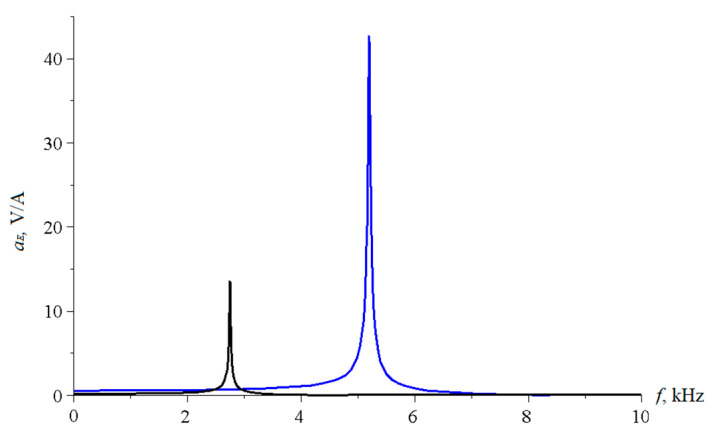
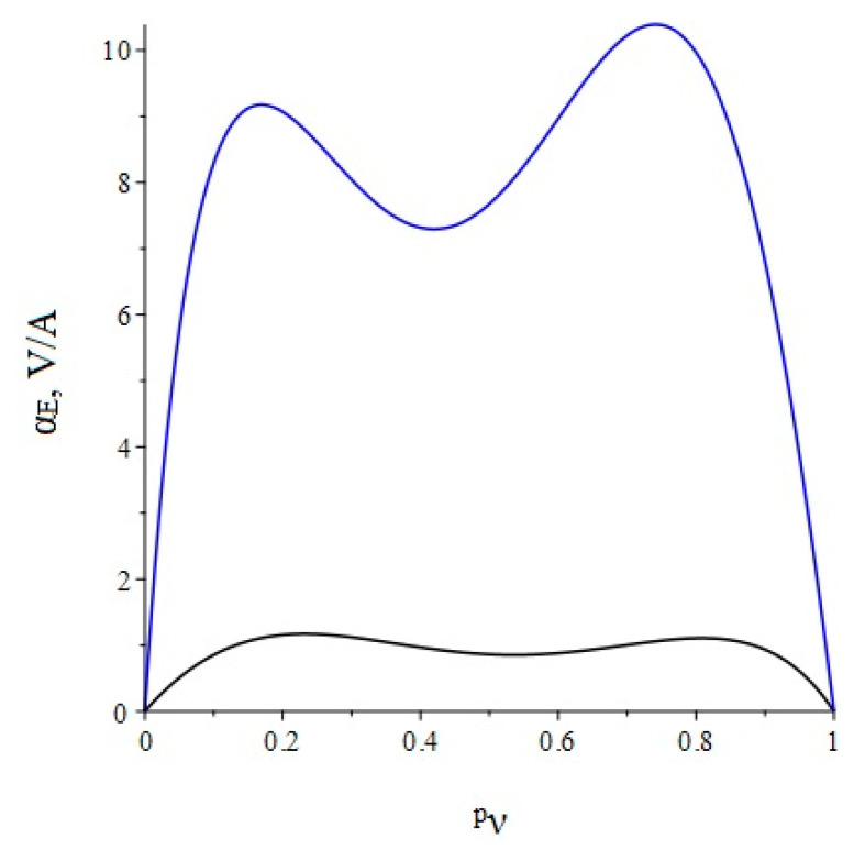
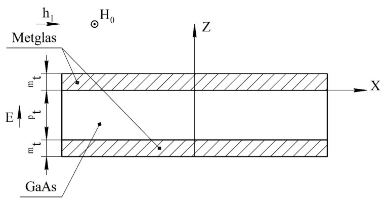
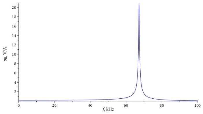
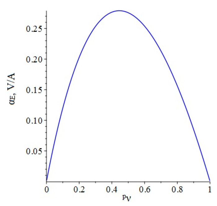
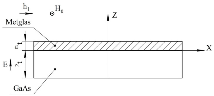
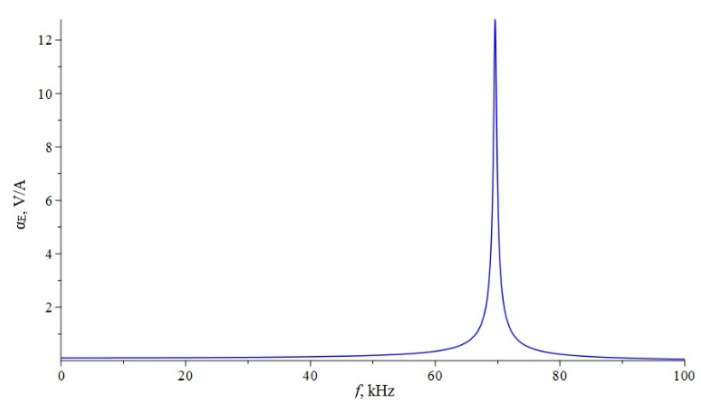
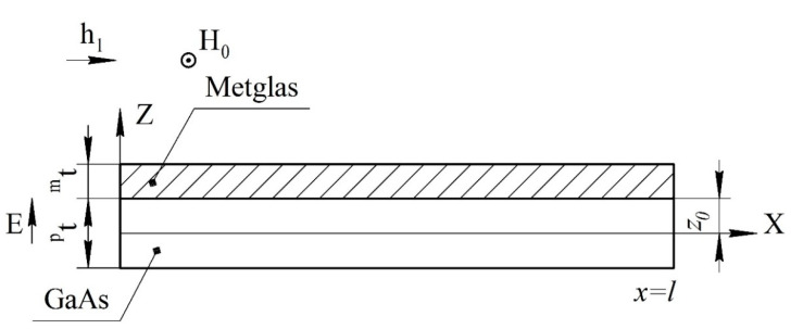
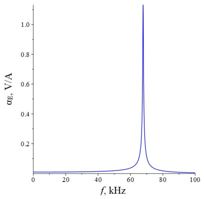
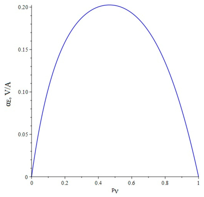
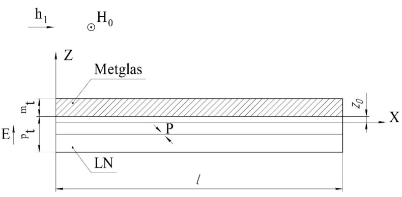
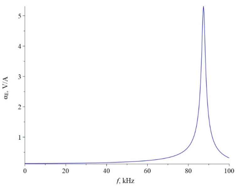
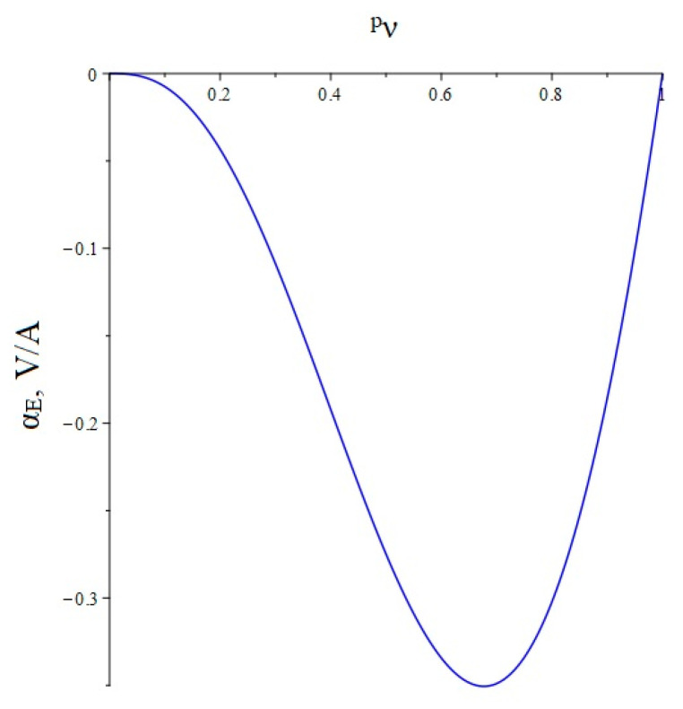
The article discusses the physical foundations of the application of the linear magnetoelectric (ME) effect in composites for devices in the low-frequency range, including the electromechanical resonance (EMR) region. The main theoretical expressions for the ME voltage coefficients in the case of a symmetric and asymmetric composite structure in the quasi-static and resonant modes are given. The area of EMR considered here includes longitudinal, bending, longitudinal shear, and torsional modes. Explanations are given for finding the main resonant frequencies of the modes under study. Comparison of theory and experimental results for some composites is given.

Keywords: electromechanical resonance; magnetoelectric composite; magnetoelectric effect; magnetoelectric voltage coefficient; resonance mode.


Conflict of interest statement

The authors declare no conflict of interest.

Figures

Figure 1
Figure 1
Symmetric tri-layer magnetoelectric composite for the calculation of longitudinal mode. Magnetic fields are parallel to each other and lie in the plane of structure, the electric field is perpendicular to the plane of structure, and pt and mt are the thicknesses of piezoelectric and magnetostrictive layers.
Figure 2
Figure 2
Theoretical dependence of the ME voltage coefficient on the frequency of the alternating magnetic field. Black color of the line is PZT, blue is LN cut y + 128°.
Figure 3
Figure 3
Theoretical dependence of the ME voltage coefficient on the volume fraction of the piezoelectric. Black color of the line is PZT, blue is LN cut y + 128°.
Figure 4
Figure 4
Asymmetrical two-layer magnetoelectric composite for calculation of longitudinal and bending modes. All designations are the same as in Figure 1.
Figure 5
Figure 5
The position of the boundary between the piezoelectric and magnetostrictive phases relative to the neutral line in a two-layer composite.
Figure 6
Figure 6
Theoretical dependence of the ME voltage coefficient on the frequency of the alternating magnetic field. Black color of the line is PZT, blue is LN cut y + 128°.
Figure 7
Figure 7
Theoretical dependence of the ME voltage coefficient on the frequency of the alternating magnetic field. Black color of the line is PZT, blue is LN cut y + 128°.
Figure 8
Figure 8
Theoretical dependence of the ME voltage coefficient on the volume fraction of the piezoelectric. Black color of the line is PZT, blue is LN cut y + 128°.
Figure 9
Figure 9
Symmetric tri-layer magnetoelectric composite for calculations of longitudinal-shear mode. In contrast to Figure 1, the magnetic fields are mutually perpendicular to each other.
Figure 10
Figure 10
Theoretical dependence of the ME voltage coefficient on the frequency of the alternating magnetic field for symmetrical ME structure Metglas/GaAs of the longitudinal-shear mode.
Figure 11
Figure 11
Theoretical dependence of the ME voltage coefficient on the volume fraction of the piezoelectric material for ME structure Metglas/GaAs of the longitudinal-shear mode.
Figure 12
Figure 12
Asymmetric two-layer magnetoelectric composite for calculation of longitudinal-shear mode. All designations are the same as in Figure 9.
Figure 13
Figure 13
Theoretical dependence of the ME voltage coefficient on the frequency of the alternating magnetic field for asymmetrical ME structure Metglas/GaAs of the longitudinal-shear mode.
Figure 14
Figure 14
Asymmetric two-layer magnetoelectric composite for calculation of torsional mode.
Figure 15
Figure 15
Theoretical dependence of the ME voltage coefficient on the frequency of the alternating magnetic field for ME structure Metglas/GaAs of the torsional mode.
Figure 16
Figure 16
Theoretical dependence of the ME voltage coefficient on the volume fraction of the piezoelectric material for the asymmetric ME structure Metglas/GaAs for the quasi-static mode of the torsional and longitudinal-shear modes.
Figure 17
Figure 17
Asymmetric magnetoelectric composite with bimorth LiNbO3 layer at torsional vibrations.
Figure 18
Figure 18
Theoretical dependence of the ME voltage coefficient on the frequency of the alternating magnetic field for ME structure Metglas/LiNbO3 Zyl + 45° in case of torsional mode.
Figure 19
Figure 19
Theoretical dependence of the ME voltage coefficient on the volume fraction of the piezoelectric material for the asymmetric ME structure Metglas/LiNbO3 Zyl + 45° for the quasi-static torsional mode.

References

    1. Nan C.-W., Bichurin M.I., Dong S., Viehland D., Srinivasan G. Multiferroic magnetoelectric composites: Historical perspectives, status, and future directions. J. Appl. Phys. 2008;103:031101. doi: 10.1063/1.2836410. - DOI
    1. Bichurin M.I., Viehland D. Magnetoelectricity in Composites. Pan Stanford Publishing Pte. Ltd.; Singapore: 2012. 273p
    1. Bichurin M.I., Petrov V.M., Petrov R.V., Tatarenko A.S. Magnetoelectric Composites. Pan Stanford Publishing Pte. Ltd.; Singapore: 2019. 280p
    1. Harshe G., Dougherty J.O., Newnham R.E. Theoretical modelling of multilayer magnetoelectric composites. Int. J. Appl. Electromagn. Mater. 1993;4:145.
    1. Bichurin M.I., Petrov V.M., Srinivasan G. Theory of low-frequency magnetoelectric coupling in magnetostrictive-piezoelectric bilayers. Phys. Rev. 2003;68:054402. doi: 10.1103/PhysRevB.68.054402. - DOI

LinkOut - more resources