. 2022 Jun 22:16:922086.
doi: 10.3389/fnins.2022.922086. eCollection 2022.

Transient Response and Firing Behaviors of Memristive Neuron Circuit

Affiliations

Transient Response and Firing Behaviors of Memristive Neuron Circuit

Xiaoyan Fang et al. Front Neurosci. .

Abstract

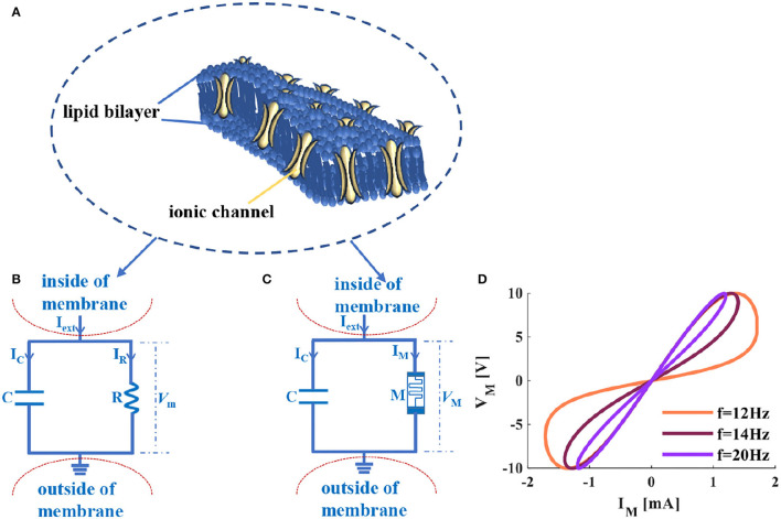
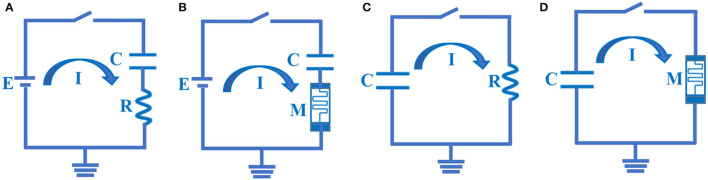
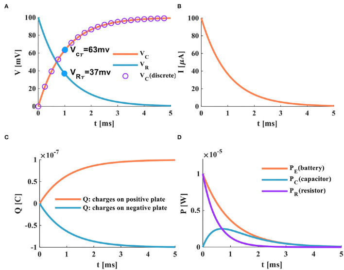
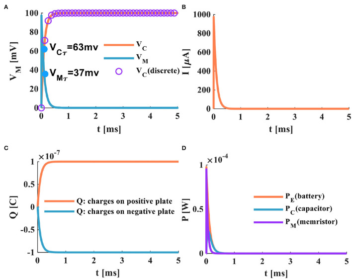
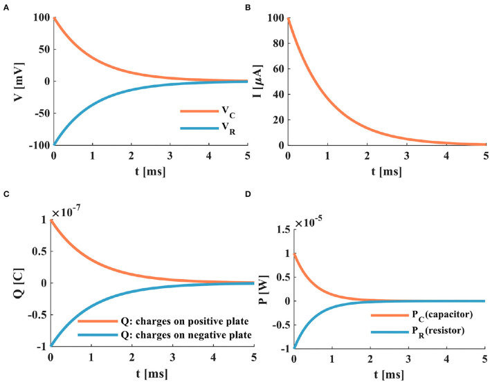
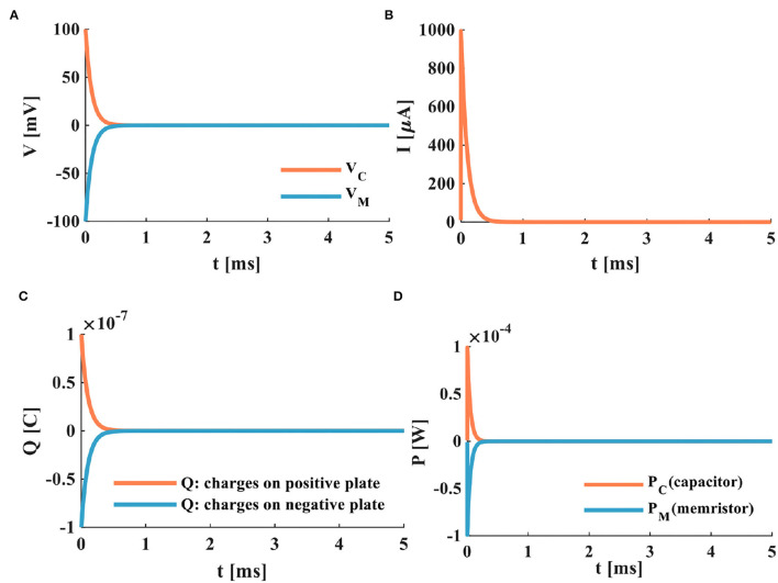
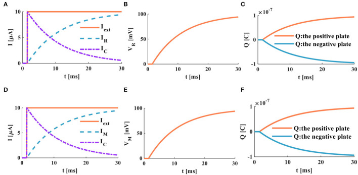
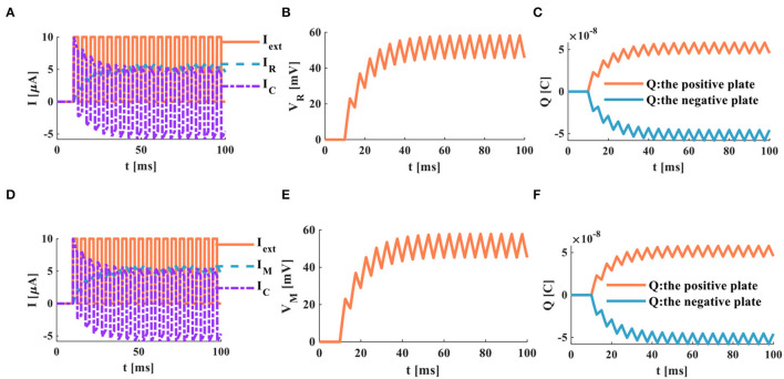
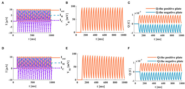
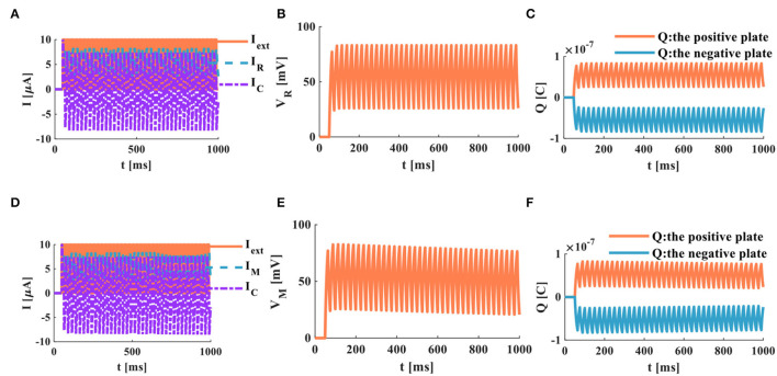
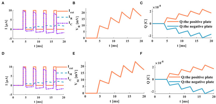
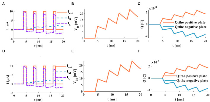
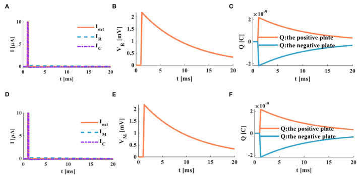
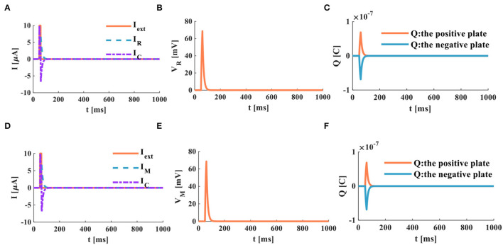
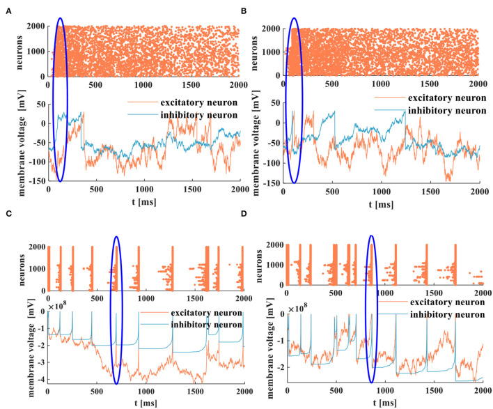
The signal transmission mechanism of the Resistor-Capacitor (RC) circuit is similar to the intracellular and extracellular signal propagating mechanism of the neuron. Thus, the RC circuit can be utilized as the circuit model of the neuron cell membrane. However, resistors are electronic components with the fixed-resistance and have no memory properties. A memristor is a promising neuro-morphological electronic device with nonvolatile, switching, and nonlinear characteristics. First of all, we consider replacing the resistor in the RC neuron circuit with a memristor, which is named the Memristor-Capacitor (MC) circuit, then the MC neuron model is constructed. We compare the charging and discharging processes between the RC and MC neuron circuits. Secondly, two models are compared under the different external stimuli. Finally, the synchronous and asynchronous activities of the RC and MC neuron circuits are performed. Extensive experimental results suggest that the charging and discharging speed of the MC neuron circuit is faster than that of the RC neuron circuit. Given sufficient time and proper external stimuli, the RC and MC neuron circuits can produce the action potentials. The synchronous and asynchronous phenomena in the two neuron circuits reproduce nonlinear dynamic behaviors of the biological neurons.

Keywords: MC circuit; RC circuit; firing behaviors; memristor; neuron.


Conflict of interest statement

The authors declare that the research was conducted in the absence of any commercial or financial relationships that could be construed as a potential conflict of interest.

Figures

Figure 1
Figure 1
The cellular membrane of a neuron and its circuit models, (A) the diagram of the voltage-controlled ionic channel cell membrane, (B) the RC circuit of the neuron membrane, (C) the MC circuit of the neuron membrane, (D) the voltage-current relationship of a memristor.
Figure 2
Figure 2
The RC and MC charging – discharging circuits. (A) The RC charging circuit. (B) The MC charging circuit. (C) The RC discharging circuit. (D) The MC discharging circuit.
Figure 3
Figure 3
The charging process of the RC neuron circuit, (A) the charging process of the capacitor, (B) the charging current of the RC neuron circuit, (C) the changing of charges on positive and negative plates of the membrane capacitor, (D) the power variation of the RC neuron circuit.
Figure 4
Figure 4
The charging process of the MC neuron circuit, (A) the membrane capacitor charging process, (B) the charging current of the MC neuron circuit, (C) the changing of charges on positive and negative plates of the membrane capacitor, (D) the power variation of the MC neuron circuit.
Figure 5
Figure 5
The discharging process of the RC neuron circuit, (A) the membrane capacitor discharging process, (B) the discharging current of the RC neuron circuit, (C) the charges on positive and negative plates of the membrane capacitor, (D) the power variation of the RC neuron circuit.
Figure 6
Figure 6
The discharging process of the MC neuron circuit, (A) the membrane capacitor discharging process, (B) the discharging current of the MC neuron circuit, (C) the discharging of charges on positive and negative plates of the membrane capacitor, (D) the power variation of the MC neuron circuit.
Figure 7
Figure 7
The step current acts on the RC and MC neuron circuits, (A) the current flows through the resistor R and the capacitor C, (B) the membrane potential of the RC circuit, (C) the charges on the positive and negative plates in the RC circuit, (D) the current flows through the memristor M and the capacitor C, (E) the membrane potential of the MC circuit, (F) the charges on the positive and negative plates in the MC circuit.
Figure 8
Figure 8
A series of current pulses act on the RC and MC neuron circuits, (A) the current flows through the resistor R and the capacitor C, (B) the membrane potential of the RC circuit, (C) the charges on the positive and negative plates in the RC circuit, (D) the current flows through the memristor M and the capacitor C. (E) the membrane potential of the MC circuit, (F) the charges on the positive and negative plates in the MC circuit.
Figure 9
Figure 9
A series of current pulses act on the RC and the MC neuron circuits (the number of external stimuli is 16), (A) the current flows through the resistor R and the capacitor C, (B) the membrane potential of the RC circuit, (C) the charges on the positive and negative plates in the RC circuit, (D) the current flows through the memristor M and the capacitor C, (E) the membrane potential of the MC circuit, (F) the charges on the positive and negative plates in the MC circuit.
Figure 10
Figure 10
A series of current pulses act on the RC and MC neuron circuits (the number of external stimuli is 38), (A) the current flows through the resistor R and the capacitor C, (B) the membrane potential of the RC circuit, (C) the charges on the positive and negative plates in the RC circuit, (D) the current flows through the memristor M and the capacitor C, (E) the membrane potential of the MC circuit, (F) the charges on the positive and negative plates in the MC circuit.
Figure 11
Figure 11
A series of current pulses act on the RC and MC neuron circuits (the number of external stimuli is 4), (A) the current flows through the resistor R and the capacitor C, (B) the membrane potential of the RC circuit, (C) the charges on the positive and negative plates in the RC circuit, (D) the current flows through the memristor M and the capacitor C, (E) the membrane potential of the MC circuit, (F) the charges on the positive and negative plates in the MC circuit.
Figure 12
Figure 12
A series of current pulses act on the RC and the MC neuron circuits (the number of the external stimuli is 4, the action time is 1, 000ms), (A) the current flows through the resistor R and the capacitor C, (B) the membrane potential of the RC circuit, (C) the charges on the positive and negative plates in the RC circuit, (D) the current flows through the memristor M and the capacitor C, (E) the membrane potential of the MC circuit, (F) the charges on the positive and negative plates in the MC circuit.
Figure 13
Figure 13
A single pulse acts on the RC and MC neuron circuits, (A) the current flows through the resistor R and the capacitor C, (B) the membrane potential of the RC circuit, (C) the charges on the positive and negative plates in the RC circuit, (D) the current flows through the memristor M and the capacitor C, (E) the membrane potential of the MC circuit, (F) the charges on the positive and negative plates in the MC circuit.
Figure 14
Figure 14
A single pulse acts on the RC and the MC neuron circuits, (A) the current flows through the resistor R and the capacitor C, (B) the membrane potential of the RC circuit, (C) the charges on the positive and negative plates in the RC circuit, (D) the current flows through the memristor M and the capacitor C, (E) the membrane potential of the MC circuit, (F) the charges on the positive and negative plates in the MC circuit.
Figure 15
Figure 15
The spike raster and the membrane potentials of the RC and the MC neuron models, (A) the asynchronous behaviors and the membrane potential of the RC neuron model, (B) the asynchronous behaviors and the membrane potential of the MC neuron model, (C) the synchronous behaviors and the membrane potential of the RC neuron model, (D) the synchronous behaviors and the membrane potential of the MC neuron model.

Similar articles

References

    1. Adapa A. K., Bhowmick S., John V. (2020). Low-frequency dc-link capacitor current mitigation in reduced switch count single-phase to three-phase converter. IEEE Trans. Ind. Electron. 68, 3058–3068. 10.1109/TIE.2020.2977543 - DOI
    1. Adhikari S. P., Yang C., Kim H., Chua L. O. (2012). Memristor bridge synapse-based neural network and its learning. IEEE Trans. Neural Netw. Learn. Syst. 23, 1426–1435. 10.1109/TNNLS.2012.2204770 - DOI - PubMed
    1. Azghadi M. R., Linares-Barranco B., Abbott D., Leong P. H. W. (2017). A hybrid cmos-memristor neuromorphic synapse. IEEE Trans. Biomed. Circ. Syst. 11, 434–445. 10.1109/TBCAS.2016.2618351 - DOI - PubMed
    1. Ballweg S., Sezgin E., Doktorova M. (2020). Regulation of lipid saturation without sensing membrane fluidity. Nat. Commun. 11, 756–768. 10.1038/s41467-020-14528-1 - DOI - PMC - PubMed
    1. Bao H., Hu A., Liu W., Bao B. (2020). Hidden bursting firings and bifurcation mechanisms in memristive neuron model with threshold electromagnetic induction. IEEE Trans. Neural Netw. Learn. Syst. 31, 502–511. 10.1109/TNNLS.2019.2905137 - DOI - PubMed

LinkOut - more resources