

VCSEL pair used as optical pointers in a contact lens for gaze tracking and visual target designation
- PMID: 35816475
- PMCID: PMC9273061
- DOI: 10.1371/journal.pone.0267393
VCSEL pair used as optical pointers in a contact lens for gaze tracking and visual target designation
Abstract
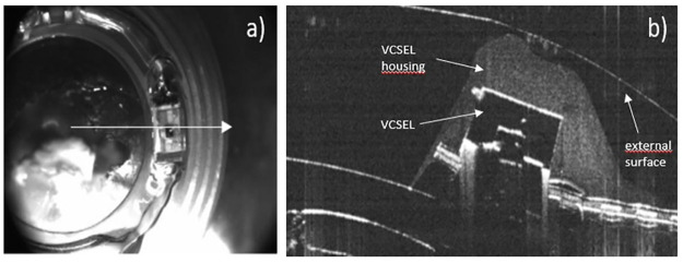
We present a new eye-tracking and target designation device based on a contact lens incorporating a pair of vertical-cavity surface-emitting lasers (VCSELs). We describe the operating principle, the manufacturing process and characterize the impact of the VCSELs encapsulation on their optical properties. We then describe how such device can be incorporated into an eye-wear or a visual augmented system. We compare two different detection set-ups, the first using a camera and the second a position sensitive device, both illustrating different laser beam detection modes. We analyze their performances in terms of angular accuracy, speed, compactness, manufacturability, compared to current conventional eye-tracking systems. We emphasize how the use of two VCSELs and the control of their orientation during the encapsulation can simplify their integration in host systems and improve the gaze detection performance. Finally, we describe various embodiments and discuss potential improvements that can be expected in future systems.
Conflict of interest statement
The authors have declared that no competing interests exist.
Figures


Similar articles
-
Contact lens embedded holographic pointer.Sci Rep. 2023 Apr 27;13(1):6919. doi: 10.1038/s41598-023-33420-8. Sci Rep. 2023. PMID: 37106122 Free PMC article.
-
A laser emitting contact lens for eye tracking.Sci Rep. 2020 Sep 9;10(1):14804. doi: 10.1038/s41598-020-71233-1. Sci Rep. 2020. PMID: 32908167 Free PMC article.
-
Metasurface-integrated vertical cavity surface-emitting lasers for programmable directional lasing emissions.Nat Nanotechnol. 2020 Feb;15(2):125-130. doi: 10.1038/s41565-019-0611-y. Epub 2020 Jan 13. Nat Nanotechnol. 2020. PMID: 31932760
-
Challenges and Advancement of Blue III-Nitride Vertical-Cavity Surface-Emitting Lasers.Micromachines (Basel). 2021 Jun 9;12(6):676. doi: 10.3390/mi12060676. Micromachines (Basel). 2021. PMID: 34207796 Free PMC article. Review.
-
Optical considerations for scleral contact lenses: A review.Cont Lens Anterior Eye. 2019 Dec;42(6):598-613. doi: 10.1016/j.clae.2019.04.012. Epub 2019 May 1. Cont Lens Anterior Eye. 2019. PMID: 31054807 Review.
Cited by
-
Design of a Multimodal Oculometric Sensor Contact Lens.Sensors (Basel). 2022 Sep 6;22(18):6731. doi: 10.3390/s22186731. Sensors (Basel). 2022. PMID: 36146080 Free PMC article.
-
Contact lens embedded holographic pointer.Sci Rep. 2023 Apr 27;13(1):6919. doi: 10.1038/s41598-023-33420-8. Sci Rep. 2023. PMID: 37106122 Free PMC article.
-
Instrumented Contact Lens to Detect Gaze Movements Independently of Eye Blinks.Transl Vis Sci Technol. 2024 Nov 4;13(11):12. doi: 10.1167/tvst.13.11.12. Transl Vis Sci Technol. 2024. PMID: 39535746 Free PMC article.
-
Potential of a laser pointer contact lens to improve the reliability of video-based eye-trackers in indoor and outdoor conditions.J Eye Mov Res. 2024 May 16;17(1):10.16910/jemr.17.1.5. doi: 10.16910/jemr.17.1.5. eCollection 2024. J Eye Mov Res. 2024. PMID: 38818405 Free PMC article.
References
-
- Nazareth RP, Kim JH, The Impact of Eye Tracking Technology, in Advances in Usability, User Experience, Wearable and Assistive Technology, T. Ahram and C. Falcão, eds., Advances in Intelligent Systems and Computing (Springer International Publishing, 2020), pp. 524–530.
-
- Palinko O, Kun AL, Shyrokov A, Heeman P, Estimating cognitive load using remote eye tracking in a driving simulator, in Proceedings of the 2010 Symposium on Eye-Tracking Research & Applications—ETRA ‘10 (ACM Press, 2010), p. 141.
-
- Bednarik R, Bartczak P, Vrzakova H, Koskinen J, Elomaa A.-P, Huotarinen A et al., Pupil size as an indicator of visual-motor workload and expertise in microsurgical training tasks, in Proceedings of the 2018 ACM Symposium on Eye Tracking Research & Applications (ACM, 2018), pp. 1–5.
-
- Kim J, Jeong Y, Stengel M, Akşit K, Albert R, Boudaoud B, et al.., Foveated AR: dynamically-foveated augmented reality display," ACM Trans. Graph. 38, 1–15 (2019).
Publication types
MeSH terms
LinkOut - more resources
Full Text Sources
Other Literature Sources
Medical
