. 2020 Dec 1;8(4):041013.
doi: 10.1115/1.4049780. Epub 2021 Feb 12.

Laser Sharpening of Carbon Fiber Microelectrode Arrays for Brain Recording

Affiliations
Free PMC article

Laser Sharpening of Carbon Fiber Microelectrode Arrays for Brain Recording

Tianshu Dong et al. J Micro Nanomanuf. .
Free PMC article

Abstract

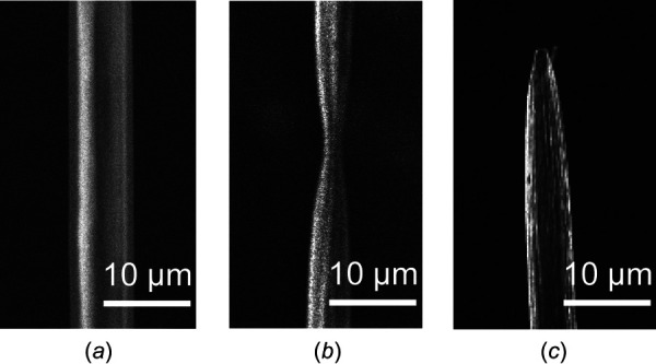
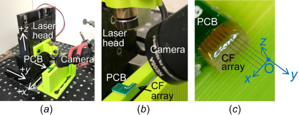
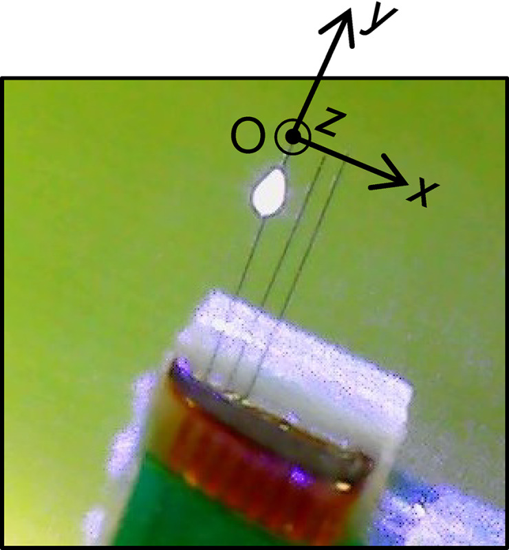
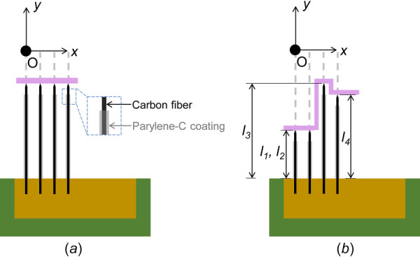
Microwire microelectrode arrays (MEAs) are implanted in the brain for recording neuron activities to study the brain function. Among various microwire materials, carbon fiber stands out due to its small diameter (5-10 μm), relatively high Young's modulus, and low electrical resistance. Microwire tips in MEAs are often sharpened to reduce the insertion force and prevent the thin microwires from buckling. Currently, carbon fiber MEAs are sharpened by either torch burning, which limits the positions of wire tips to a water bath surface plane, or electrical discharge machining, which is difficult to implement to the nonelectrically conductive carbon fiber with parylene-C insulation. A laser-based carbon fiber sharpening method proposed in this study enables the fabrication of carbon fiber MEAs with sharp tips and custom lengths. Experiments were conducted to study effects of laser input voltage and transverse speed on carbon fiber tip geometry. Results of the tip sharpness and stripped length of the insulation as well as the electrochemical impedance spectroscopy measurement at 1 kHz were evaluated and analyzed. The laser input voltage and traverse speed have demonstrated to be critical for the sharp tip, short stripped length, and low electrical impedance of the carbon fiber electrode for brain recording MEAs. A carbon fiber MEA with custom electrode lengths was fabricated to validate the laser-based approach.


Figures

Three sample carbon fiber MEAs (a) a bundle of 16 carbon fiber electrodes [13], (b) 2 × 8 carbon fiber array [11], and (c) 32 channel carbon fiber array assembled by Massey et al.
Fig. 1
Three sample carbon fiber MEAs (a) a bundle of 16 carbon fiber electrodes [13], (b) 2 × 8 carbon fiber array [11], and (c) 32 channel carbon fiber array assembled by Massey et al.
Sharp tip of metal microwire: (a) stainless steel microwire by chemical etching [31] and (b) tungsten microwire by ECM with KOH solution
Fig. 2
Sharp tip of metal microwire: (a) stainless steel microwire by chemical etching [31] and (b) tungsten microwire by ECM with KOH solution
Carbon fiber sharpening methods and outcomes: (a) setup, (b) outcome of the torch burning method [13], (c) schematic diagram, and (d) outcome of EDM sharpening of carbon fiber [33]
Fig. 3
Carbon fiber sharpening methods and outcomes: (a) setup, (b) outcome of the torch burning method [13], (c) schematic diagram, and (d) outcome of EDM sharpening of carbon fiber [33]
SEM pictures of the carbon fiber with parylene-C insulation: (a) before cutting, (b) partial cutoff at 25 μm/s and 4 DCV laser input voltage, and (c) fully cutoff with sharpened conical tip at 20 μm/s and 4 DCV laser input voltage
Fig. 4
SEM pictures of the carbon fiber with parylene-C insulation: (a) before cutting, (b) partial cutoff at 25 μm/s and 4 DCV laser input voltage, and (c) fully cutoff with sharpened conical tip at 20 μm/s and 4 DCV laser input voltage
Experimental setup: (a) overview of the three-axis motion system, stationary camera and PCB, (b) close-up view of the laser head, camera and PCB, and (c) camera view of the 1 × 4 carbon fiber array on the PCB
Fig. 5
Experimental setup: (a) overview of the three-axis motion system, stationary camera and PCB, (b) close-up view of the laser head, camera and PCB, and (c) camera view of the 1 × 4 carbon fiber array on the PCB
The light spot on the carbon fiber when the laser beam hit the carbon fiber
Fig. 6
The light spot on the carbon fiber when the laser beam hit the carbon fiber
Schematic diagram of laser path: (a) path I for Experiments I and II (0.2 mm pitch between two adjacent fibers) and (b) Path II for Experiment III
Fig. 7
Schematic diagram of laser path: (a) path I for Experiments I and II (0.2 mm pitch between two adjacent fibers) and (b) Path II for Experiment III
Evaluation metrics for (a) tip profile L1, L2, and L3: the distances between tip and the positions which correspond to D2 = 0.2D1, 0.5D1, and 0.8D1, (b) tip angle α, and (c) stripped length S: the distance from the tip to the end of the stripped region
Fig. 8
Evaluation metrics for (a) tip profile L1, L2, and L3: the distances between tip and the positions which correspond to D2 = 0.2D1, 0.5D1, and 0.8D1, (b) tip angle α, and (c) stripped length S: the distance from the tip to the end of the stripped region
Four tips from (a) 5, (b) 4, and (c) 2.5 DCV input. Serrated asymmetric profiles were observed.
Fig. 9
Four tips from (a) 5, (b) 4, and (c) 2.5 DCV input. Serrated asymmetric profiles were observed.
Tip geometry under three laser power levels: tip profile L1, L2, L3, tip angle α and stripped length S
Fig. 10
Tip geometry under three laser power levels: tip profile L1, L2, L3, tip angle α and stripped length S
Experiment III results: (a) snapshots of ongoing cutting and sharpening process to get an array of carbon fiber in different lengths (with l1 = 1.2 mm, l2 = 1.2 mm, l3 = 1.6 mm, and l4 = 1.4 mm in Fig. 6) and (b) SEM image of the array
Fig. 11
Experiment III results: (a) snapshots of ongoing cutting and sharpening process to get an array of carbon fiber in different lengths (with l1 = 1.2 mm, l2 = 1.2 mm, l3 = 1.6 mm, and l4 = 1.4 mm in Fig. 6) and (b) SEM image of the array

Similar articles

Cited by

References

    1. Drachman, D. A. , 2005, “ Do We Have Brain to Spare?,” Neurology, 64(12), pp. 2004–2005.10.1212/01.WNL.0000166914.38327.BB - DOI - PubMed
    1. Henze, D. A. , Borhegyi, Z. , Csicsvari, J. , Mamiya, A. , Harris, K. D. , and Buzsáki, G. , 2000, “ Intracellular Features Predicted by Extracellular Recordings in the Hippocampus In Vivo,” J. Neurophysiol., 84(1), pp. 390–400.10.1152/jn.2000.84.1.390 - DOI - PubMed
    1. Burle, B. , Spieser, L. , Roger, C. , Casini, L. , Hasbroucq, T. , and Vidal, F. , 2015, “ Spatial and Temporal Resolutions of EEG: Is It Really Black and White? A Scalp Current Density View,” Int. J. Psychophysiol., 97(3), pp. 210–220.10.1016/j.ijpsycho.2015.05.004 - DOI - PMC - PubMed
    1. Dale, A. M. , Liu, A. K. , Fischl, B. R. , Buckner, R. L. , Belliveau, J. W. , Lewine, J. D. , and Halgren, E. , 2000, “ Dynamic Statistical Parametric Mapping: Combining FMRI and MEG for High-Resolution Imaging of Cortical Activity,” Neuron, 26(1), pp. 55–67.10.1016/S0896-6273(00)81138-1 - DOI - PubMed
    1. Drake, K. L. , Wise, K. D. , Farraye, J. , Anderson, D. J. , and BeMent, S. L. , 1988, “ Performance of Planar Multisite Microprobes in Recording Extracellular Single-Unit Intracortical Activity,” IEEE Trans. Biomed. Eng., 35(9), pp. 719–732.10.1109/10.7273 - DOI - PubMed

LinkOut - more resources