

A Novel Model of Ultrasonic Fatigue Test in Pure Bending
- PMID: 35888332
- PMCID: PMC9317056
- DOI: 10.3390/ma15144864
A Novel Model of Ultrasonic Fatigue Test in Pure Bending
Abstract
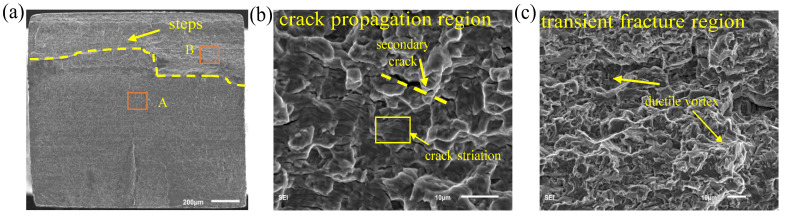
The very high cycle fatigue (VHCF) failure of in-service components is mainly caused by the vibration of thin-wall elements at a high frequency. In this work, a novel model of ultrasonic fatigue test was developed to test thin-wall material in bending up to VHCF with an accelerated frequency. The theoretical principle and finite element analysis were introduced for designing a sample that resonated at the frequency of 20 kHz in flexural vibration. In the advantage of the second-order flexural vibration, the gauge section of the sample was in the pure bending condition which prevented the intricate stress condition for thin-wall material as in the root of cantilever or the contact point of three points bending. Moreover, combining the constraint and the loading contact in one small section significantly reduced heating that originated from the friction at an ultrasonic frequency. Both strain gauge and deflection angle methods were applied to verify the controlling of stress amplitude. The fractography observation on Ti6Al4V samples indicated that the characterized fracture obtained from the novel model was the same as that from the conventional bending test.
Keywords: experimental method; flexural vibration; thin plate material; very high cycle fatigue.
Conflict of interest statement
The authors declare no conflict of interest.
Figures


References
-
- Tien J.K. The State of Ultrasonic Fatigue. Int. J. Fatigue. 1982;4:238.
-
- Brugger C., Palin-Luc T., Osmond P., Blanc M. Gigacycle Fatigue Behavior of a Cast Aluminum Alloy Under Biaxial Bending: Experiments with a New Piezoelectric Fatigue Testing Device. Procedia Struct. Integr. 2016;2:1173–1180.
-
- Hopkinson B. A High-Speed Fatigue-Tester, and the Endurance of Metals Under Alternating Stresses of High Frequency. Proc. R. Soc. London. Ser. A Contain. Pap. A Math. Phys. Character. 1912;86:131–149.
-
- Jenkin C.F., Lehmann G.D. High Frequency Fatigue. Proc. R. Soc. London. Ser. A Contain. Pap. A Math. Phys. Character. 1929;125:83–119.
-
- Mason W.P., Baerwald H. Piezoelectric Crystals and their Applications to Ultrasonics. Phys. Today. 1951;4:23.
Grants and funding
LinkOut - more resources
Full Text Sources
