Review
. 2022 Jul 6;27(14):4330.
doi: 10.3390/molecules27144330.

Photothermal-Driven Liquid Crystal Elastomers: Materials, Alignment and Applications

Affiliations
Review

Photothermal-Driven Liquid Crystal Elastomers: Materials, Alignment and Applications

Wei Zhang et al. Molecules. .

Abstract

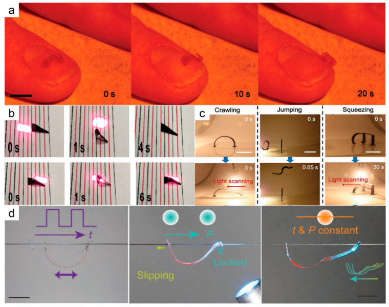
Liquid crystal elastomers (LCEs) are programmable deformable materials that can respond to physical fields such as light, heat, and electricity. Photothermal-driven LCE has the advantages of accuracy and remote control and avoids the requirement of high photon energy for photochemistry. In this review, we discuss recent advances in photothermal LCE materials and investigate methods for mechanical alignment, external field alignment, and surface-induced alignment. Advances in the synthesis and orientation of LCEs have enabled liquid crystal elastomers to meet applications in optics, robotics, and more. The review concludes with a discussion of current challenges and research opportunities.

Keywords: actuator; liquid crystal elastomer; smart material; soft robot.


Conflict of interest statement

The authors declare no conflict of interest.

Figures

Figure 1
Figure 1
(a) Schematic of liquid crystal polymers, liquid crystal polymer networks and liquid crystal elastomers; (b) Schematic illustration of the contraction along the alignment of LCEs when heated beyond TNI.
Figure 2
Figure 2
Synthetic route for two-step cross-linked LCE chemistry. (a) Two-step crosslinking by hydrosilylation; (b) aza-Michael addition between diacrylate-based RMs and amines; (c) thiol-Michael addition of diacrylate-based RMs and thiols.
Figure 3
Figure 3
LCE composites. (a) CNT/LCE composite material (Reprinted with permission from Ref. [24]. Copyright 2008, John Wiley and Sons). (b) Graphene/LCE composite material (Reprinted with permission from Ref. [28]. Copyright 2015, John Wiley and Sons). (c) Metal nanomaterial/LCE composite material (Reprinted with permission from Ref. [30]. Copyright 2015, John Wiley and Sons).
Figure 4
Figure 4
(a) Schematic diagram of LCE alignment by tensile stress. Mesogens will be aligned parallel to the direction of tensile stress. (b) Schematic diagram of LCE alignment by compressive stress. LC molecules will be oriented vertically according to the direction of the compressive stress.
Figure 5
Figure 5
Schematic of direct ink writing (DIW) using shear stress aligned LCE. Mesogens will be aligned parallel to the direction of shear stress.
Figure 6
Figure 6
(a) Schematic representation of LCE alignment by electric field. (b) Schematic representation of LCE alignment by magnetic field.
Figure 7
Figure 7
Schematic diagram of making an oriented substrate and surface-induced orientation of LCE. (a) Liquid crystal molecules aligned by layer; (b) fabrication of oriented substrates by friction; (c) production of oriented substrates by photosensitive materials and light sources with pattern information; (d) microchannels are formed on the substrate surface by lithography.
Figure 8
Figure 8
(a) Schematic diagram of the structure changing in an LCE-based inverse opal membrane with increasing temperature (Reprinted with permission from Ref. [82]. Copyright 2011, American Chemical Society). (b) Reversible driving behavior and reflectance spectrum shift of SiO2 opal PC/LCE composite films (Reprinted with permission from Ref. [80]. Copyright 2016, American Chemical Society). (c) Schematic diagram and demonstration of self-oscillation of two-segment photonic crystal thin films under visible light (Reprinted with permission from Ref. [83]. Copyright 2018, John Wiley and Sons).
Figure 9
Figure 9
(a) Bionic light-powered artificial Venus flytrap robot and its working principle (Reprinted with permission from Ref. [5]. Copyright 2017, Springer Nature). (b) Light-driven LCE device simulating human iris structure and its negative feedback mechanism schematic (Reprinted with permission from Ref. [37]. Copyright 2017, John Wiley and Sons). (c) A light-controlled robot that can simulate the jumping of gall midge larvae and its energy storage and release mechanism (Reprinted with permission from Ref. [85]. Copyright 2021, John Wiley and Sons). (d) A snail-inspired LCE robot and its movement principle (Reprinted with permission from Ref. [84]. Copyright 2019, John Wiley and Sons).
Figure 10
Figure 10
(a) Caterpillar robot crawling on a human fingernail under the irradiation of a 488 nm laser (Reprinted with permission from Ref. [87]. Copyright 2018, John Wiley and Sons). (b) Image of a trapezoidal LCE robot crawling forward and backward under near-infrared light (Reprinted with permission from Ref. [93]. Copyright 2022, American Chemical Society). (c) Multimodal locomotion of a soft robot powered by light (Reprinted with permission from Ref. [27]. Copyright 2019, John Wiley and Sons); (d) A robot moves along a hair in different patterns. One is friction control, which uses light to lock and slide between the legs and the other is a self-oscillating mode (Reprinted with permission from Ref. [89]. Copyright 2022, John Wiley and Sons).
Figure 11
Figure 11
(a) A soft robot moving forward and backward under a continuous wave green laser (Reprinted with permission from Ref. [86]. Copyright 2016, John Wiley and Sons). (b) Schematic diagram of a multi-directional soft robot, and images of it crawling under three wavelengths of light (Reprinted with permission from Ref. [7]. Copyright 2019, Springer Nature). (c) A light-driven soft robot moving around (multi-directional) a palm tree (Reprinted with permission from Ref. [91]. Copyright 2020, John Wiley and Sons).
Figure 12
Figure 12
(a) Light-induced deformation schematic diagram of a tensegrity robot and demonstration of zigzag and gyro rolling of the robot under irradiation with a NIR laser (Reprinted with permission from Ref. [96]. Copyright 2019, John Wiley and Sons). (b) Design of a light-driven rolling robot, and images of the robot climbing a 6° hill (Reprinted with permission from Ref. [97]. Copyright 2020, John Wiley and Sons).
Figure 13
Figure 13
(a) Light-driven swimming of a soft robot based on an LCE film coated with PDA, and the schematic diagram of its actuation principle (Reprinted with permission from Ref. [35]. Copyright 2018, American Chemical Society). (b) Vertical locomotion of a soft robot underwater reported by Hamed Shahsavan et al. (Reprinted with permission from Ref. [99]. Copyright 2020,National Academy of Sciences).
Figure 14
Figure 14
(a) Schematic diagram of an indigo dye-doped LCE film self-oscillating in sunlight (Reprinted with permission from Ref. [100]. Copyright 2017, John Wiley and Sons). (b) Oscillation images of dichromatic dye-doped LCE films at different θ (0°, 30°, 60°, and 90°) and a fixed laser power density (40 mW cm−2) (Reprinted with permission from Ref. [8]. Copyright 2020, John Wiley and Sons). (c) Schematic diagram of self-masking oscillation of a PDA-coated liquid crystal polymer film (Reprinted with permission from Ref. [36]. Copyright 2020, John Wiley and Sons). (d) The process of light-driven motion and deformation of a composites film under the irradiation of a NIR laser (Reprinted with permission from Ref. [101]. Copyright 2022, American Chemical Society). (e) Schematic diagram of a miniature solar generator (Reprinted with permission from Ref. [36]. Copyright 2020, John Wiley and Sons).
Figure 15
Figure 15
(a) Images of an LCE film lifting up a binder clip and load under NIR light illumination (left) and the preparation process of the film (right) (Reprinted with permission from Ref. [107]. Copyright 2017, American Chemical Society). (b) Schematic and image of an LCE fiber arm lifting a heavy object (Reprinted with permission from Ref. [110]. Copyright 2021, the American Association for the Advancement of Science).

References

    1. De Gennes P.G. Possibilites Offertes par la Reticulation de Polymeres en Presence D’un Cristal Liquide. Phys. Lett. A. 1969;28:725–726. doi: 10.1016/0375-9601(69)90584-2. - DOI
    1. Thomsen D.L., Keller P., Naciri J., Pink R., Jeon H., Shenoy D., Ratna B.R. Liquid Crystal Elastomers with Mechanical Properties of a Muscle. Macromolecules. 2001;34:5868–5875. doi: 10.1021/ma001639q. - DOI
    1. Ware T.H., McConney M.E., Wie J.J., Tondiglia V.P., White T.J. Voxelated Liquid Crystal Elastomers. Science. 2015;347:982–984. doi: 10.1126/science.1261019. - DOI - PubMed
    1. White T.J., Broer D.J. Programmable and Adaptive Mechanics with Liquid Crystal Polymer Networks and Elastomers. Nat. Mater. 2015;14:1087–1098. doi: 10.1038/nmat4433. - DOI - PubMed
    1. Wani O.M., Zeng H., Priimagi A. A Light-driven Artificial Flytrap. Nat. Commun. 2017;8:15546. doi: 10.1038/ncomms15546. - DOI - PMC - PubMed

LinkOut - more resources