. 2022 Jul 23;12(15):2537.
doi: 10.3390/nano12152537.

All-Dielectric Transreflective Angle-Insensitive Near-Infrared (NIR) Filter

Affiliations

All-Dielectric Transreflective Angle-Insensitive Near-Infrared (NIR) Filter

Ayesha Shaukat et al. Nanomaterials (Basel). .

Abstract

This paper presents an all-dielectric, cascaded, multilayered, thin-film filter, allowing near-infrared filtration for spectral imaging applications. The proposed design is comprised of only eight layers of amorphous silicon (A-Si) and silicon nitride (Si3N4), successively deposited on a glass substrate. The finite difference time domain (FDTD) simulation results demonstrate a distinct peak in the near-infrared (NIR) region with transmission efficiency up to 70% and a full-width-at-half-maximum (FWHM) of 77 nm. The theoretical results are angle-insensitive up to 60∘ and show polarization insensitivity in the transverse magnetic (TM) and transverse electric (TE) modes. The theoretical response, obtained with the help of spectroscopic ellipsometry (SE), is in good agreement with the experimental result. Likewise, the experimental results for polarization insensitivity and angle invariance of the thin films are in unison with the theoretical results, having an angle invariance up to 50∘.

Keywords: FDTD; NIR filter; angle invariance; spectroscopic ellipsometry; thin films.


Conflict of interest statement

The authors declare no conflict of interest.

Figures

Figure 1
Figure 1
Response of incident light in 1D ternary photonic crystal with low (Si3N4) and high A-Si refractive indices layers.
Figure 2
Figure 2
(a) A hybrid etalon when cavity thickness du=dl = d = 40 nm and h=100 nm. (b) SEM image of hybrid etalon. (c) Refractive indices of silicon nitride (Si3N4); and (d) amorphous silicon (A-Si).
Figure 3
Figure 3
Theoretical (dotted line) and measured (solid line) results for (a) transmission and (b) reflection spectra of hybrid etalon with d = 40 nm and h = 100 nm.
Figure 4
Figure 4
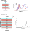
(a) Schematic of hybrid etalon and its transmission spectrum at different cavity thicknesses such that dn=d1, d2, and d3, where d1=d=80 nm is the fundamental cavity thickness, while d2 and d3 are its multiples; (b) schematic of multilayered thin-film cascaded filter and transmission spectrum of its theoretical and experimental results, where d1=d=80 nm is the fundamental thickness of cavity, while d2 and d3 are its multiples.
Figure 5
Figure 5
(a) SEM image; and (b) transmission spectrum of measured and theoretical results of multilayered thin-film cascaded filter.
Figure 6
Figure 6
The ellipsometric experiment’s measurement geometry. In the p-s coordinate system, the coordinate system is used to describe the ellipse of polarization. The s direction is defined as parallel to the sample surface and perpendicular to the direction of propagation. The p direction is assumed to be perpendicular to the direction of propagation and lies inside the plane of incidence. The plane of incidence (gray area) is defined as the plane including the input and output beams and the direction which is normal to the sample surface.
Figure 7
Figure 7
Flow chart for ellipsometry data analysis.
Figure 8
Figure 8
Ellipsometric fit to the proposed design extracted at 55°, 65°, and 75°.
Figure 9
Figure 9
Theoretical and experimental results for multilayered cascaded thin-film filter.
Figure 10
Figure 10
Transmission spectrum produced with the help of simulated, experimental, and ellipsometry-derived data.
Figure 11
Figure 11
Simulated results of the designed filter at different source incident angles in (a) TM and (c) TE polarization mode. Transmission profile at different incident angles the incident light in (b) TM and (d) TE mode obtained with the help of spectroscopic ellipsometry.
Figure 12
Figure 12
Response of cascaded multilayered thin-film filter in transmission and reflection mode.

References

    1. ElMasry G., ElGamal R., Mandour N., Gou P., Al-Rejaie S., Belin E., Rousseau D. Emerging thermal imaging techniques for seed quality evaluation: Principles and applications. Food Res. Int. 2020;131:109025. doi: 10.1016/j.foodres.2020.109025. - DOI - PubMed
    1. Liu J. Smoothing filter-based intensity modulation: A spectral preserve image fusion technique for improving spatial details. Int. J. Remote Sens. 2000;21:3461–3472. doi: 10.1080/014311600750037499. - DOI
    1. Hook S.J., Johnson W.R., Abrams M.J. Thermal Infrared Remote Sensing. Springer; Berlin/Heidelberg, Germany: 2013. NASA’s hyperspectral thermal emission spectrometer (HyTES) pp. 93–115.
    1. Zheng Z., Luo Y., Yang H., Yi Z., Zhang J., Song Q., Yang W., Liu C., Wu X., Wu P. Thermal tuning of terahertz metamaterial absorber properties based on VO2. Phys. Chem. Chem. Phys. 2022;24:8846–8853. doi: 10.1039/D2CP01070D. - DOI - PubMed
    1. Modir N., Shahedi M., Dormer J., Fei B. High-Speed Biomedical Imaging and Spectroscopy VI. SPIE; Bellingham, WA, USA: Development of a real-time spectral imaging system using in-site LED-based illumination for endoscopic applications. - PMC - PubMed

LinkOut - more resources