Review
. 2022 Nov;63(11):2782-2801.
doi: 10.1111/epi.17381. Epub 2022 Sep 3.

Decision-making in stereotactic epilepsy surgery

Affiliations
Review

Decision-making in stereotactic epilepsy surgery

Kai J Miller et al. Epilepsia. 2022 Nov.

Abstract

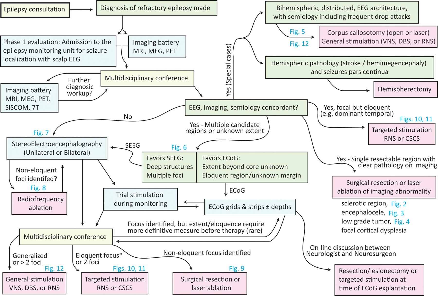
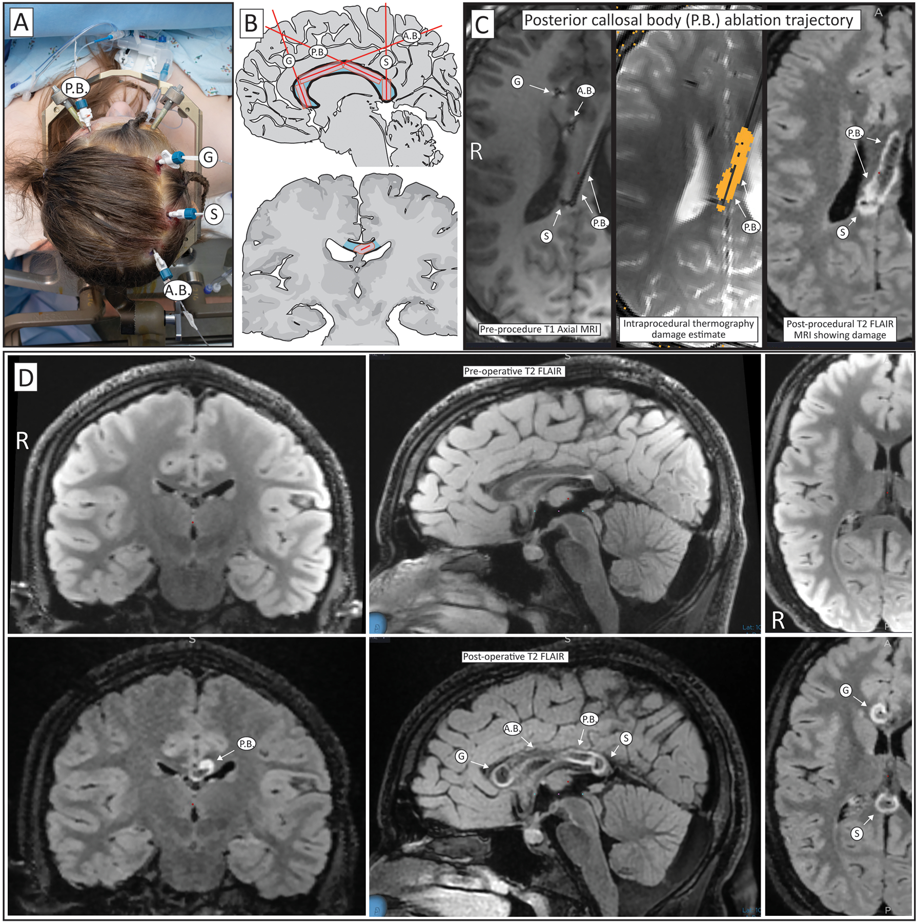
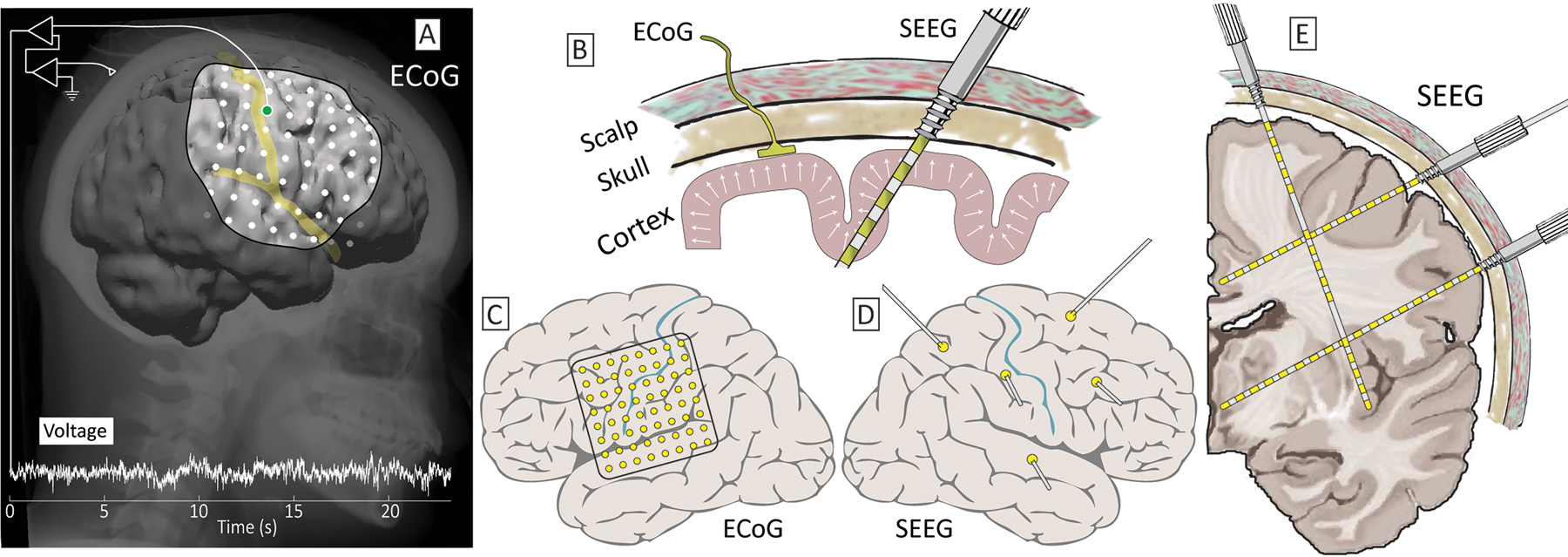
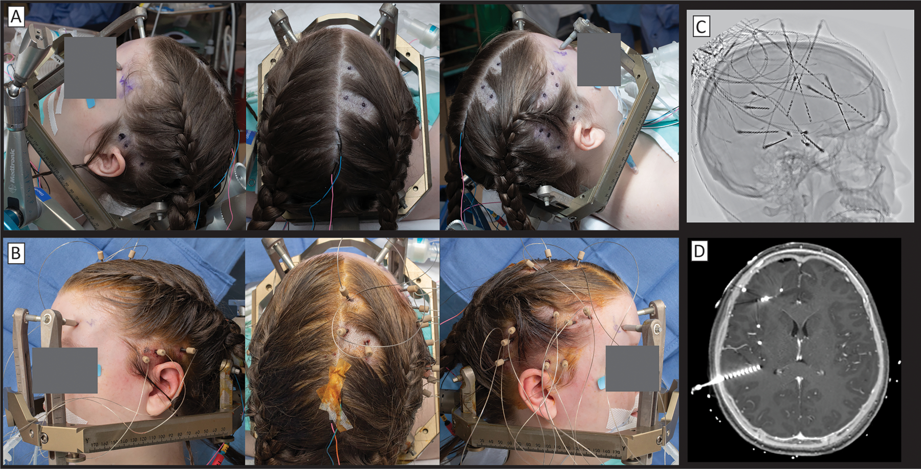
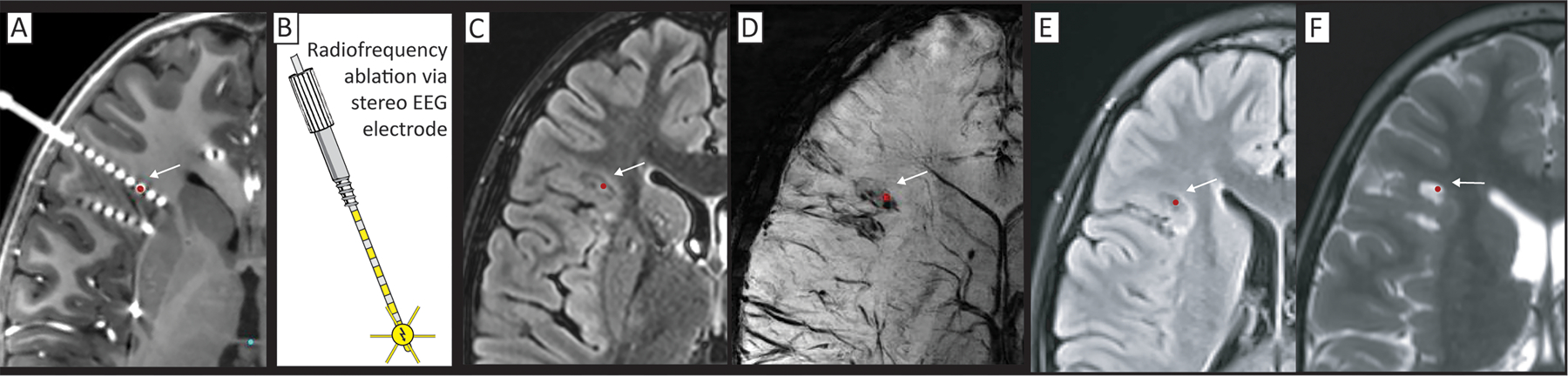
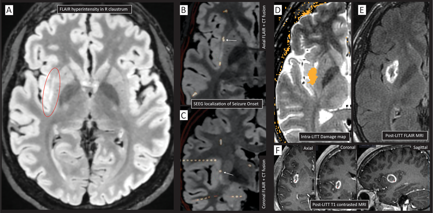
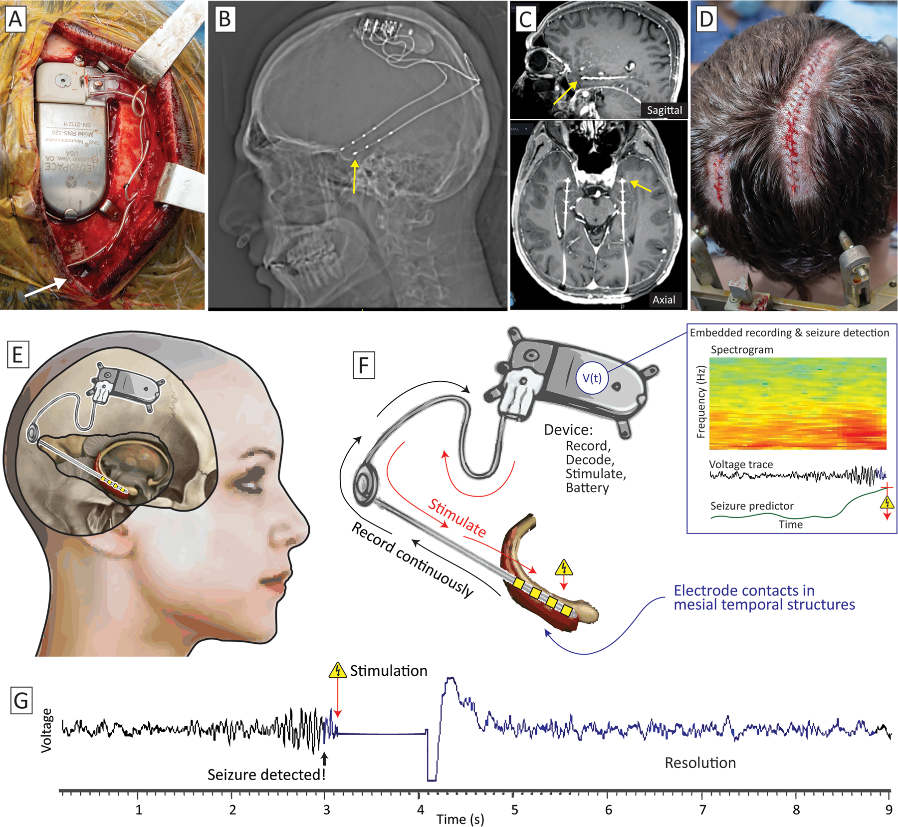
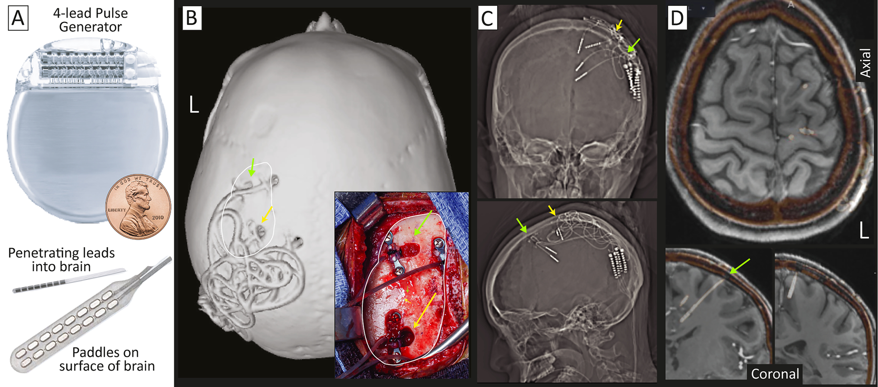
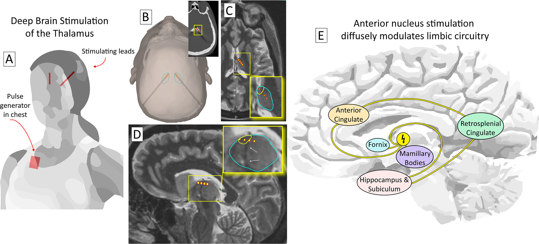
Surgery can cure or significantly improve both the frequency and the intensity of seizures in patients with medication-refractory epilepsy. The set of diagnostic and therapeutic interventions involved in the path from initial consultation to definitive surgery is complex and includes a multidisciplinary team of neurologists, neurosurgeons, neuroradiologists, and neuropsychologists, supported by a very large epilepsy-dedicated clinical architecture. In recent years, new practices and technologies have emerged that dramatically expand the scope of interventions performed. Stereoelectroencephalography has become widely adopted for seizure localization; stereotactic laser ablation has enabled more focal, less invasive, and less destructive interventions; and new brain stimulation devices have unlocked treatment of eloquent foci and multifocal onset etiologies. This article articulates and illustrates the full framework for how epilepsy patients are considered for surgical intervention, with particular attention given to stereotactic approaches.

Keywords: epilepsy; neurosurgery; stereotaxy.


Figures

Figure 1:
Figure 1:
Overview of the decision-making process in stereotactic epilepsy surgery. The process begins in the top left, with a consultation to the epileptologist. Steps illustrated in this manuscript are noted by corresponding figure number.
Figure 2:
Figure 2:. Dual filament LITT ablation for mesial temporal sclerosis.
(A) Coronal (top) and axial (bottom) T2 MRI showing left hippocampal mesial temporal sclerosis. Sclerotic hippocampus indicated by red arrow. (B) The transparent laser cannula is continually cooled with cycled saline and held in place with a skull alignment and anchoring bolt that can be entirely plastic (as seen here), or metal & plastic (seen in C). (C) The mesial temporal structures are targeted with two cannulas. One is from a posterior approach (yellow-dashed), targeting the body and lateral head of the hippocampus, and the other is from a lateral approach, targeting the amygdala and the superior-medial aspect of the hippocampal head. (D) The posterior-approach laser cannula seen by air artifact on in-plane pseudo-coronal (top) and pseudo-axial (bottom) T2 MRI, indicated by yellow arrows. Green arrows show the lateral approach cannula, which can also be seen on the coronal image. (E) Thermal damage map from the posterior cannula in pseudo-coronal (top) and axial (bottom) sections. (F) As in D&E, but for the lateral approach cannula, indicated in green arrows. Note the ablation from the posterior approach (yellow arrow) that can be seen on the coronal image. (G) Post-ablation damage revealed on T1 post-contrast (gadolinium) MRI, in coronal (left), axial (right), and sagittal (bottom) sections.
Figure 3:
Figure 3:. Illustration of laser interstitial thermal therapy (LITT) for a left temporal encephalocele.
(A) A left anteromedial temporal skull base defect can is seen on 3D rendering (red arrow). (B) The skull defect and herniating brain tissue is seen in coronal section. (C) Operative photograph showing site of cannula insertion through skull bolt. (D) Realtime image of temperature map from MR thermography (modified T2* sequence). (E) Realtime cumulative damage map for estimated permanent burn using the Arrhenius equation. (F) Sequential ablations - realtime MRI thermography (from white box in (D). (G) Sequential cumulative damage map (from white box in (E).
Figure 4:
Figure 4:. Coordinated biopsy and LITT of an epileptogenic tumor.
(A&B) A child with intractable seizures was found to have a right-sided lingual gyrus lesion, seen here in T1&T2 axial sections. (C) Diffusion tractography imaging (DTI) showed close proximity of the lesion to the optic radiations. (D) Three laser cannulas were placed stereotactically. A needle biopsy was performed through the posterior trajectory prior to cannula placement, and the lesion was found to be a dysembryoplastic neuroepithelial tumor (DNET). (E-G) Damage maps for 3 laser trajectories. (H&I) Post-ablation damage revealed on contrasted (gadolinium) T1 (H) and T2 (I) MRIs.
Figure 5:
Figure 5:. Complete corpus callosotomy performed by four-cannula LITT approach.
(A) Four skull bolts are placed with an anterior-posterior posterior callosal body (P.B.) trajectory, transverse trajectories through the genu (G) and splenium (S), and a posterior-anterior anterior callosal body (A.B.) trajectory. (B) Segments of the corpus callosum traversed by laser cannulas in cartoonized sagittal (upper) and coronal (lower) images. (C) Illustration using axial FLAIR MRI imaging of an ablation trajectory in post-placement, pre-treatment imaging where artifact from air shows the cannulas (left), during the treatment where the estimated damage can be seen in orange (middle), and post-treatment, where the ablated region can be seen with hyperintensity. (D) Pre-operative (top) and post-treatment (bottom) FLAIR imaging in coronal (left), sagittal (middle), and axial (right) sections, showing the ablation extent.
Fig 6.
Fig 6.. Electrocorticography (ECoG) and stereoelectroencephalography (SEEG).
(A) Grids of brain surface ECoG electrodes are placed through large openings in the skull (craniotomies). (B) Recently, there has been increasing use of stereotactically-placed depth electrodes – SEEG, placed through bolts embedded in the skull. (C) ECoG electrodes sample the exposed, convexity, brain surface at regular intervals. (D) SEEG samples this convexity irregularly and sparsely, though can be targeted precisely. (E) SEEG is used to precisely sample surface & deep gray matter as well as subcortical nuclei to identify seizure onset zones and potential therapeutic loci.
Fig 7.
Fig 7.. Stereoelectroencephalography implantation.
(A) Preoperatively, insertion sites are marked and small shaves are made. (B) SEEG bolts are placed stereotactically and SEEG leads are advanced in-line through them. (C) An inverted x-ray shows a variety of trajectories. Note that many surgeons are increasingly placing “skew” trajectories that follow gyral anatomy rather than pure lateral trajectories that dominated in Europe in previous generations. (D) Fusion of CT to post-gadolinium enhancement T1 MRI shows the precise relationship of each electrode to underlying brain anatomy.
Fig 8.
Fig 8.. Radiofrequency ablation (RF) through stereoelectroencephalography electrodes.
(A) Seizure onset was identified by SEEG in several of the deepest contacts, centered at the red dot, and indicated by an arrow (on CT fused to gadolinium-contrasted T1). (B) RF ablation is performed by passing current directly through the SEEG electrodes, using a grounding pad on the leg. (C-D) Immediate post-procedure MR imaging on T2 FLAIR (C), and susceptibility-weighting (D). (E&F) 16-month post-procedure T2 FLAIR (E) and standard T2 (F) showing persistent lesion effect.
Fig 9.
Fig 9.. Peri-insular seizure onset zone intervention.
(A) A hyperintensity is seen on MR FLAIR sequence in the right claustrum (circled in red), but scalp EEG non-focal within the right hemisphere. (B&C) Implanted SEEG electrodes (white-orange) fused to the FLAIR MRI localized seizure initiation (white arrow) to the claustrum/insula (B-axial, C-coronal). RF ablation changed seizure semiology, though did not eliminate seizures altogether. (D) Based upon causal suggestion from RF, LITT was performed, with intraoperative damage estimate (orange) overlaid on axial T2 MRI. (E) Post-LITT axial FLAIR MRI. (F) Post-LITT gadolinium-contrasted T1 MRI seen in axial, coronal, and sagittal sections. Note that the peri-insular seizures were also captured in electrodes out of plane in addition to that noted by white arrow in panels C&D.
Fig 10.
Fig 10.. Responsive neurostimulation (RNS), illustrated for bitemporal epilepsy with for the Neuropace system.
(A) The sense & stimulate device is embedded in a tray in the right parietal boss of the skull, and leads are placed stereotactically (insertion site the right lead shown with a white arrow). (B) Lateral x-ray shows leads bilaterally. (C) Fused post-implant CT to gadolinium-contrasted T1 MRI in sagittal (upper panel) and axial (lower panel) planes, showing the leads traversing the hippocampus and extending into the anterior-inferior portion of the amygdala. (D) Incisions for device implantation, with the left incision for insertion and anchoring of left lead, and the closed right incision from (A). (E) Schematic of implantation from a right-sided view showing a common trajectory (here terminating in the hippocampus). (F) Data are recorded continuously from the implanted structure and processed in the RNS device. When the custom-parameterized predictor exceeds a threshold (indicating seizure detection), electrical stimulation pulses are sent back into the lead. (G) Example voltage trace from an implanted patient, showing emergence of a seizure, stimulation, and resolution of the seizure.
Fig 11.
Fig 11.. Constant subthreshold cortical stimulation (CSCS) of two spatially-separated SOZs.
(A) Co-opted pulse generators typically used for DBS are used to deliver electrical current into the seizure network using paddle or penetrating lead electrodes. Target sites within the seizure network are initially identified with ECoG or SEEG. (B) An example implant with penetrating leads, seen on a skull surface rendering and intraoperative photograph (inset, with corresponding skull surface indicated by white trace). (C) AP and lateral x-rays showing penetrating leads. (D) Co-registered Implanted SEEG electrodes (white-orange) fused to the gadolinium-contrasted T1 MRI show implantation in the primary and pre-motor areas. Yellow and green indicate corresponding sites in (B-D).
Fig 12.
Fig 12.. Deep brain stimulation to treat epilepsy.
(A) A deep brain stimulation system consists of stimulating electrodes that target central brain structures connected to a pulse generator (placed in the chest). (B) The thalamus may be approached from a posterior-to-anterior trajectory, as illustrated, or a superior-to-inferior trajectory through the ventricle. Inset shows electrode positions on post-implant CT. (C) The anterior nucleus of thalamus (ANT - yellow encircled region within blue encircled thalamus in inset) is the most common target for deep brain stimulation. A trajectory is shown with 4 contacts in the thalamus, 2 of which lie within the ANT, in axial section. (D) The same trajectory as (C), but in sagittal section. The ANT lies immediately superior to the termination of the mammillothalamic tract (white arrows). (E) Because of its diffuse projections, DBS of the ANT is thought to suppress seizures throughout the limbic network, despite not targeting the sites of seizure onset directly.

Similar articles

Cited by

References

    1. Kwan P, Brodie MJ. Early identification of refractory epilepsy N Engl J Med 2000. Feb 3;342:314–319. - PubMed
    1. Callaghan BC, Anand K, Hesdorffer D, Hauser WA, French JA. Likelihood of seizure remission in an adult population with refractory epilepsy Ann Neurol 2007. Oct;62:382–389. - PubMed
    1. Luciano AL, Shorvon SD. Results of treatment changes in patients with apparently drug-resistant chronic epilepsy Ann Neurol 2007. Oct;62:375–381. - PubMed
    1. Kwan P, Schachter SC, Brodie MJ. Drug-resistant epilepsy N Engl J Med 2011. Sep 8;365:919–926. - PubMed
    1. Jobst BC, Cascino GD. Resective epilepsy surgery for drug-resistant focal epilepsy: a review JAMA 2015. Jan 20;313:285–293. - PubMed

Publication types