

Characterization and correction of diffusion gradient-induced eddy currents in second-order motion-compensated echo-planar and spiral cardiac DTI
- PMID: 35916545
- PMCID: PMC9804234
- DOI: 10.1002/mrm.29378
Characterization and correction of diffusion gradient-induced eddy currents in second-order motion-compensated echo-planar and spiral cardiac DTI
Abstract
Purpose: Very high gradient amplitudes played out over extended time intervals as required for second-order motion-compensated cardiac DTI may violate the assumption of a linear time-invariant gradient system model. The aim of this work was to characterize diffusion gradient-related system nonlinearity and propose a correction approach for echo-planar and spiral spin-echo motion-compensated cardiac DTI.
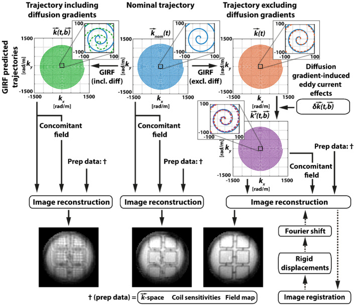
Methods: Diffusion gradient-induced eddy currents of 9 diffusion directions were characterized at b values of 150 s/mm2 and 450 s/mm2 for a 1.5 Tesla system and used to correct phantom, ex vivo, and in vivo motion-compensated cardiac DTI data acquired with echo-planar and spiral trajectories. Predicted trajectories were calculated using gradient impulse response function and diffusion gradient strength- and direction-dependent zeroth- and first-order eddy current responses. A reconstruction method was implemented using the predicted -space trajectories to additionally include off-resonances and concomitant fields. Resulting images were compared to a reference reconstruction omitting diffusion gradient-induced eddy current correction.
Results: Diffusion gradient-induced eddy currents exhibited nonlinear effects when scaling up the gradient amplitude and could not be described by a 3D basis alone. This indicates that a gradient impulse response function does not suffice to describe diffusion gradient-induced eddy currents. Zeroth- and first-order diffusion gradient-induced eddy current effects of up to -1.7 rad and -16 to +12 rad/m, respectively, were identified. Zeroth- and first-order diffusion gradient-induced eddy current correction yielded improved image quality upon image reconstruction.
Conclusion: The proposed approach offers correction of diffusion gradient-induced zeroth- and first-order eddy currents, reducing image distortions to promote improvements of second-order motion-compensated spin-echo cardiac DTI.
Keywords: EPI; GIRF; cardiac DTI; eddy currents; image reconstruction; spiral imaging.
© 2022 The Authors. Magnetic Resonance in Medicine published by Wiley Periodicals LLC on behalf of International Society for Magnetic Resonance in Medicine.
Figures


Similar articles
-
Characterization and correction of time-varying eddy currents for diffusion MRI.Magn Reson Med. 2022 May;87(5):2209-2223. doi: 10.1002/mrm.29124. Epub 2021 Dec 11. Magn Reson Med. 2022. PMID: 34894640
-
Eddy current-induced artifact correction in high b-value ex vivo human brain diffusion MRI with dynamic field monitoring.Magn Reson Med. 2024 Feb;91(2):541-557. doi: 10.1002/mrm.29873. Epub 2023 Sep 27. Magn Reson Med. 2024. PMID: 37753621 Free PMC article.
-
A field-monitoring-based approach for correcting eddy-current-induced artifacts of up to the 2nd spatial order in human-connectome-project-style multiband diffusion MRI experiment at 7T: A pilot study.Neuroimage. 2020 Aug 1;216:116861. doi: 10.1016/j.neuroimage.2020.116861. Epub 2020 Apr 16. Neuroimage. 2020. PMID: 32305565 Free PMC article.
-
k-space correction of eddy-current-induced distortions in diffusion-weighted echo-planar imaging.Magn Reson Med. 2005 May;53(5):1103-11. doi: 10.1002/mrm.20429. Magn Reson Med. 2005. PMID: 15844088
-
Spiral imaging in fMRI.Neuroimage. 2012 Aug 15;62(2):706-12. doi: 10.1016/j.neuroimage.2011.10.039. Epub 2011 Oct 20. Neuroimage. 2012. PMID: 22036995 Free PMC article. Review.
Cited by
-
Cardiac DTI using short-axis PROPELLER: A feasibility study.Magn Reson Med. 2024 Jun;91(6):2546-2558. doi: 10.1002/mrm.30020. Epub 2024 Feb 20. Magn Reson Med. 2024. PMID: 38376096 Free PMC article.
-
Maximizing SNR per unit time in diffusion MRI with multiband T-Hex spirals.Magn Reson Med. 2024 Apr;91(4):1323-1336. doi: 10.1002/mrm.29953. Epub 2023 Dec 29. Magn Reson Med. 2024. PMID: 38156527 Free PMC article.
-
Cardiac diffusion-weighted and tensor imaging: A consensus statement from the special interest group of the Society for Cardiovascular Magnetic Resonance.J Cardiovasc Magn Reson. 2025 Summer;27(1):101109. doi: 10.1016/j.jocmr.2024.101109. Epub 2024 Oct 22. J Cardiovasc Magn Reson. 2025. PMID: 39442672 Free PMC article.
-
Giving the prostate the boost it needs: Spiral diffusion MRI using a high-performance whole-body gradient system for high b-values at short echo times.Magn Reson Med. 2025 Mar;93(3):1256-1272. doi: 10.1002/mrm.30351. Epub 2024 Nov 4. Magn Reson Med. 2025. PMID: 39497447 Free PMC article.
-
In vivo diffusion MRI of the human heart using a 300 mT/m gradient system.Magn Reson Med. 2024 Sep;92(3):1022-1034. doi: 10.1002/mrm.30118. Epub 2024 Apr 22. Magn Reson Med. 2024. PMID: 38650395 Free PMC article.
References
-
- Gotschy A, von Deuster C, Weber L, et al. CMR diffusion tensor imaging provides novel imaging markers of adverse myocardial remodeling in aortic stenosis. JACC Cardiovasc Imaging 2021;14:1472‐1474. - PubMed
Publication types
MeSH terms
LinkOut - more resources
Full Text Sources
