Review
. 2022 Oct;9(28):e2105577.
doi: 10.1002/advs.202105577. Epub 2022 Aug 9.

Advances in Emerging Photonic Memristive and Memristive-Like Devices

Affiliations
Review

Advances in Emerging Photonic Memristive and Memristive-Like Devices

Wenxiao Wang et al. Adv Sci (Weinh). 2022 Oct.

Abstract

Possessing the merits of high efficiency, low consumption, and versatility, emerging photonic memristive and memristive-like devices exhibit an attractive future in constructing novel neuromorphic computing and miniaturized bionic electronic system. Recently, the potential of various emerging materials and structures for photonic memristive and memristive-like devices has attracted tremendous research efforts, generating various novel theories, mechanisms, and applications. Limited by the ambiguity of the mechanism and the reliability of the material, the development and commercialization of such devices are still rare and in their infancy. Therefore, a detailed and systematic review of photonic memristive and memristive-like devices is needed to further promote its development. In this review, the resistive switching mechanisms of photonic memristive and memristive-like devices are first elaborated. Then, a systematic investigation of the active materials, which induce a pivotal influence in the overall performance of photonic memristive and memristive-like devices, is highlighted and evaluated in various indicators. Finally, the recent advanced applications are summarized and discussed. In a word, it is believed that this review provides an extensive impact on many fields of photonic memristive and memristive-like devices, and lay a foundation for academic research and commercial applications.

Keywords: artificial visual system; brain-like computing; memristive-like behavior; memristors; photoelectric logic; photonic memristive devices; resistive switching.


Conflict of interest statement

The authors declare no conflict of interest.

Figures
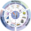
Figure 1
Figure 1
Schematic diagram of the mechanisms, materials, and applications of the photonic memristive and memristive‐like devices. Image for “photo‐generated carriers”: Reproduced with permission.[ ] Copyright 2019, Elsevier B.V. Image for “Photo‐mediated interface barrier”: Reproduced with permission.[ 101 ] Copyright 2018, American Chemical Society. Image for “Photo‐induced Formation/annihilation of Conductive Filaments”: Reproduced with permission.[ 90 ] Copyright 2018, Wiley‐VCH. Image for “Photochemical Reaction Process”: Reproduced with permission.[ 126 ] Copyright 2017, Wiley‐VCH. Image for “Metal Oxide”: Reproduced with permission.[ 145 ] Copyright 2018, American Institute of Physics. Image for “2D Materials”: Reproduced with permission.[ 99 ] Copyright 2018, Wiley‐VCH. Image for “Quantum Dots”: Reproduced with permission.[ 90 ] Copyright 2018, Wiley‐VCH. Image for “Perovskite”: Reproduced with permission.[ 100 ] Copyright 2018, Wiley‐VCH. Image for “Photo‐induced Multilevel RRAM”: Reproduced with permission.[ 258 ] Copyright 2021, Wiley‐VCH. Image for “Photoelectric Logic Operations”: Reproduced with permission.[ 7 ] Copyright 2017, American Chemical Society. Image for “Neuromorphic Computing”: Reproduced with permission.[ 292 ] Copyright 2021, American Chemical Society. Image for “Artificial Visual System”: Reproduced with permission.[ 72 ] Copyright 2021, Wiley‐VCH.
Figure 2
Figure 2
a) 3D schematic illustration of the CsPbBr3 QDs‐based photonic memristive‐like device. b) Side view of the Au/pentacene/PMMA/CsPbBr3/SiO2/Si device recorded by the cross‐sectional SEM. c) Schematic energy diagram of the device at initial state. d) Schematic energy diagram of the device during a light programming operation and electrical erasing operation under dark conditions. e) 3D schematic of the Al/ZnO/PbS QDs/ZnO/ITP structure and the conceptual drawing of the device array. f) Resistive modulation mechanisms of the Al/ZnO/PbS QDs/ZnO/ITO device in the full‐photo mode. (a–d) Reproduced with permission.[ 98 ] Copyright 2018, Wiley‐VCH. (e, f) Reproduced with permission.[ 64 ] Copyright 2019, Elsevier B.V.
Figure 3
Figure 3
a) Conceptual drawing of the ITO/Nb: SrTiO3 heterojunction artificial photonic synapse. b) Resistive switching mechanism of the ITO/Nb: SrTiO3 photonic synapse. I) Initial Schottky barrier profile. II) Schottky barrier profile after light illumination accompanied by positive voltage stress. III) Schottky barrier profile after only light illumination. IV) Schottky barrier profile after light illumination accompanied by negative voltage stress. The dashed lines in (II–IV) represent the initial energy band profile. c) Cross‐sectional SEM image of the In2O3/ZnO/FTO device. d) Band alignment at the ZnO/In2O3 interface under thermal equilibrium and photo‐induced electron‐hole pair generation and their respective trapping on the ZnO and In2O3 sides. (a, b) Reproduced with permission.[ 65 ] Copyright 2019, American Chemical Society. (c, d) Reproduced with permission.[ 101 ] Copyright 2018, American Chemical Society.
Figure 4
Figure 4
a) Schematic diagram of the Cs4PbBr6‐based photonic memristive device. b) Schematic diagram of the proposed mechanism for the operation of the Cs4PbBr6‐based photonic memristive device. I) in the initial state, II) with light and III) in dark. c) Schematic illustration of the CsPbBr3 QD‐based photonic RRAM device. d) Illustration of resistive switching at the I) initial state, II) during the set process under dark conditions, III) and during the set process under UV illumination. e) Schematic diagram of the ultra‐scaled memristive photodetector. A modulated input optical power (left panel) is converted into a digital electronic current (right panel). f) Memristive current as a function of the optical input power (black and red solid circles are experiments, and blue circles represent simulations), and the ON‐state (OFF‐state) where the filament is completely formed (dissociated). g) Schematic of the experimental setup used in this study and the inset show the structure of the HfO2‐based RRAM. h) Schematic illustration of the proposed mechanism for the light‐induced resistance reset. I) Formation of a conducting filament comprising oxygen vacancies, with the released oxygen ions populating interstitial sites in the filament vicinity. II) Partial filament disruption due to limited supply of photo‐excited migrating oxygen ions, including weakly bonded lattice oxygen in the filament vicinity. (a, b) Reproduced with permission.[ 105 ] Copyright 2019, Elsevier B.V. (c, d) Reproduced with permission.[ 90 ] Copyright 2018, Wiley‐VCH. (e, f) Reproduced with permission.[ 110 ] Copyright 2018, American Chemical Society. (g, h) Reproduced with permission.[ 111 ] Copyright 2019, American Institute of Physics.
Figure 5
Figure 5
a) Magnified image of GST on top of the waveguide, and schematic cross‐section of the completed device. b) Schematic of the optical pulse shapes used to amorphize and crystallize the integrated PCM cell. c) Simulated transmission and crystalline fraction as a function of the programming pulse energy. d) Simulated temperature distribution in the GST memory cell after a 20 ns programming pulse. e) 3D illustration of the proposed PCM concept. f) Eigenmode simulations of field enhancement inside the plasmonic nanogap when the GST is in the amorphous (top) or crystalline state (the region between Au electrodes, bottom). g) Experimental measurement of total energy in the waveguide required to achieve a nonvolatile phase transition. The switching threshold is measured to be 16 ± 2 pJ according to a linear fit to the data (black dashed line). h) Schematic illustration of the GST‐based device and the measurement setup. i) Concept diagram of the resistive switching mechanism. j) Diagram of electron transport mechanism under Ι) Amorphous and II) Crystalline. (a–d) Reproduced with permission.[ 121 ] Copyright 2019, Optica Publishing Group. (e–g) Reproduced with permission.[ 122 ] Copyright 2019, American Association for the Advancement of Science. (h–j) Reproduced with permission.[ 123 ] Copyright 2018, American Chemical Society.
Figure 6
Figure 6
a) Schematic of the photonic memristive devices consisting of PDR1A and b) the transform of PDR1A chromophores chemical structure under circularly polarized light and linearly polarized light. c) Optical modulation of the electronic switching characteristics of a ZnO/PDR1A memristive device before irradiation, directly after irradiation (20 min) with circularly polarized light and linearly polarized light. d) Optical modulation of the HRS and LRS states via repeated irradiation of circularly and linearly polarized light. e) Schematic of the photonic memristive devices consisting of Au nanoparticles (NPs) embedded within a thin film of azobenzene polymer PDR1A and deposited between ITO and Al electrodes. f) Thickness changes of a PDR1A film with time on irradiation with (red line) circularly polarized light of intensity 180 mW cm−2. g) Schematic diagram of o‐BMThCE‐based memory, and the chemical structure of the photochromic diarylethene. IV characteristics of the BMThCE‐based memories h) ITO/o‐BMThCE/Al, and i) ITO/c‐BMThCE/Al. (a–d) Reproduced with permission.[ 124 ] Copyright 2017, Royal Society of Chemistry. (e, f) Reproduced with permission.[ 125 ] Copyright 2019, Wiley‐VCH. (g–i) Reproduced with permission.[ 126 ] Copyright 2017, Wiley‐VCH.
Figure 7
Figure 7
a) Schematic representation of the Pb/Al2O3/SiO2/Si device. b) Data retention capability in dark conditions and under illumination with UV light, and IR light. c) The IV characteristics of the ITO/HfO2/TiN‐based memristor. Inset: the schematic illustrations of the ITO/HfO2/TiN‐based memristor. d) Forming voltage of ITO/HfO2/TiN‐based memristor with and without illumination. e) Schematic diagram of the photonic memristive device with ITO/CeO2− x /AlO y /Al structure. f) Mechanism for the light‐gate memristive characteristics of the device. g) Schematic illustration of the ZnO nanorods‐based device structure. h) Initial state before UV exposure and after UV exposure of the ZnO nanorods surface. (a, b) Reproduced with permission.[ 137 ] Copyright 2017, Wiley‐VCH. (c, d) Reproduced with permission.[ 141 ] Copyright 2020, IOP Science. (e, f) Reproduced with permission.[ 7 ] Copyright 2017, American Chemical Society. (g, h) Reproduced with permission.[ 145 ] Copyright 2018, American Institute of Physics.
Figure 8
Figure 8
a) Schematic of a biological synapse and photonic synapse based on monolayer MoS2. b) AFM profile of monolayer MoS2. c) The IV curves of the W/MoS2/p‐Si device. d) Schematic of free‐standing multilayer MoS2 memristive device under light illumination. e) AFM image showing the depth of the trench (200 nm) and the thickness of MoS2 (23 nm). f) Schematic of the I) planar structure and II) vertical structure optical resistive switching device consisting of GO deposited between ITO and Ag electrodes. g) Schematic showing light modulation of the BP@PS memristive device. h) IV curves of the BP@PS memristive device modulated by different wavelengths. i) Schematic of the photonic memristive device structure with the ReS2‐PVA nanocomposite. (a–c) Reproduced with permission.[ 99 ] Copyright 2018, Wiley‐VCH. (d, e) Reproduced with permission.[ 176 ] Copyright 2021, American Chemical Society. (f) Reproduced with permission.[ 128 ] Copyright 2019, Elsevier B.V. (g, h) Reproduced with permission.[ 178 ] Copyright 2020, American Chemical Society. (i) Reproduced with permission.[ 179 ] Copyright 2021, American Chemical Society.
Figure 9
Figure 9
a) Schematic illustration Laser direct writing (LDW) of the perovskite film assisted by photothermal effect. The inset shows the photo of a perovskite thin film with two stripes converted to the PVSK phase through LDW. b) Optical (top) and fluorescent (bottom) microscopy images of the micro‐lines pattern by LDW. c) Measured Raman spectra at different positions. The two distinct spectra correspond to the non‐PVSK phase (black curve) and the PVSK phase (blue curve). d) Line‐scan PL intensity of the fluorescent image in (b). e) COMSOL Multiphysics thermal simulation of heat distribution induced by a laser beam (9 mW) with a spot size of 1 µm. f) Schematic diagram of the switching device with Au/MAPbBr3/ITO structure, and AFM image of the perovskite layer surface. g) Endurance performance of the flexible RS device measured with various bending radius: 8, 6, 4, and 3 mm (from left to right). h) Proposed two‐terminal simple photonic memristive device with drain (NiO), active layer [(C4H9NH3)2PbBr4], and source (ZnO) and the schematic presentation of the three vertically stacked layers of the (C4H9NH3)2PbBr4. i) Experimentally measured absence of photo‐response under this condition‐designated OFF state and ON state. (a–e) Reproduced with permission.[ 197 ] Copyright 2018, Wiley‐VCH. (f, g) Reproduced with permission.[ 100 ] Copyright 2018, Wiley‐VCH. (h, i) Reproduced with permission.[ 205 ] Copyright 2018, Wiley‐VCH.
Figure 10
Figure 10
a) Device structure diagram and the cross‐sectional SEM image of the Ag/PbS QDs@PMMA/ITO memory device. b) TEM image of PbS QDs. c) I) Schematic of ZB hybrid NPs‐based photonic RRAM. II) Top‐viewed SEM image of ZB NPs film and III) the 3D image of ZB hybrid NPs. d) Schematic illustration of the CsPbBr3 QD‐based photonic RRAM device. e) TEM image of the CsPbBr3 QDs, inset is the diameter distribution of the QD. f) Steady‐state one‐photon‐excited (ope) (λ ex = 400 nm) PL spectra. (a, b) Reproduced with permission.[ 106 ] Copyright 2020, Royal Society of Chemistry. (c) Reproduced with permission.[ 203 ] Copyright 2018, Wiley‐VCH. (d–f) Reproduced with permission.[ 90 ] Copyright 2018, Wiley‐VCH.
Figure 11
Figure 11
a) Design of multi‐dye‐sensitized UCNPs and integration with ultrathin nonvolatile memory for advanced information security. I) Design of multi‐dye‐sensitized UCNPs for wide‐range photo‐absorption and upconversion. II) Normalized absorption and photoluminescence spectra of the UCNP, sensitizers (I), (II), (III), and normalized absorption spectrum of the PAG. III) schematic illustration of the photo‐induced unrecoverable data erasure in the ultrathin nonvolatile memory device with UCNPs. b) Cross‐sectional TEM image of the integrated system (RRAM on the Si transistor coated with UCNPs/PAG/PEO layer). c) Schematic illustration and cross‐section scanning electron microscopy image of the photonic memristive device. d) TEM image of as‐prepared MoS2‐UCNPs nanocomposite. e) Simplified energy level diagram describing upconverting PL process and MoS2 excitation process. f) Absorption spectrum of the UCNPs, MoS2, and MoS2‐UCNPs nanocomposite. g) System integration of the 13 × 13 array with light signal. h) The light signals are stored in the 13 × 13 array. (a, b) Reproduced with permission.[ 230 ] Copyright 2016, Wiley‐VCH. (c–h) Reproduced with permission.[ 49 ] Copyright 2018, Wiley‐VCH.
Figure 12
Figure 12
a) Schematic illustration of the CDs‐silk memory device. b) Cross‐sectional SEM image of the device structure. c) Schematic diagram of the device structure and the image mapping of the LTM and STM processes. d) Device scheme of the HyQN‐Cl/P3BT C60 blends and chemical structure of ferroelectric (R)‐(−)‐3‐hydroxlyquinuclidinium chloride, C60, and poly(3‐butylthiophene) (P3BT). e) Absorption of HyQN‐Cl/P3BT C60 blends. f) Device scheme and the photovoltaic switching mechanism in HyQN‐Cl/P3BT C60 devices. g) Illustration of the GST‐based PCM and measurement scheme. h) FDTD simulations of the power flow from left to right through the region of GST when GST is in both the amorphous and crystalline states. i) Experimental optical transmission of the device with increasing optical probe power. j) Device structure of Azo‐Au NPs based memristor. k) Schematic of AZO functional Au NPs. l) Schematic diagram of the Azo‐Au NPs I) before and II) after UV light irradiation. (a, b) Reproduced with permission.[ 124 ] Copyright 2017, Royal Society of Chemistry. (c) Reproduced with permission.[ 232 ] Copyright 2020, American Chemical Society. (d–f) Reproduced with permission.[ 251 ] Copyright 2019, Elsevier B.V. (g–i) Reproduced with permission.[ 237 ] Copyright 2019, Wiley‐VCH. (j–l) Reproduced with permission.[ 238 ] Copyright 2020, Royal Society of Chemistry.
Figure 13
Figure 13
a) The IV characteristics of the Pt/CeO2/Nb: SrTiO3/In RRAM. b) The retention and endurance characteristics of the device at LRS, IRS1, IRS2, and HRS. c) The retention properties of the device at LRS, IRS1, IRS2, and HRS in dark and under illumination. d) Schematic of the Ag/SPTP/PVA/FTO structured multifunctional photonic RRAM. e) Current–time response of HRS under UV light (1.5 mW cm−2) and dark conditions. f) Multilevel resistance states achieved by UV modulation with light intensities of 0, 1, 1.5, and 2.7 mW cm−2. g) Photoresponse characteristics of the PbS QDs‐based device under various laser irradiation. Light wavelengths: I) 405 nm, II) 808 nm, III) 1177 nm at various power densities. (a–c) Reproduced with permission.[ 264 ] Copyright 2018, Elsevier B.V. (d–f) Reproduced with permission.[ 258 ] Copyright 2021, Wiley‐VCH. (g) Reproduced with permission.[ 106 ] Copyright 2020, Royal Society of Chemistry.
Figure 14
Figure 14
a) Schematic diagram of the photoelectric logic RRAM with the structure of TiN/BiVO4/FTO/Glass. b) Logic gate with OR operation and the output table. c) Planar implementation of the Pt/HfO2/p‐Si devices and the IV characteristics under illumination with 450 nm light. d) Light‐controlled IMP operations I) with and II) without light illumination. e) Resistive switching of the device before and after the light at the positive voltage sweep. Inset: the log‐scale IV curve. f) Schematic diagram of the “AND” and “OR” logic operation switching of the ITO/CeO2− x /AlO y /Al memlogic devices. g) Truth table and output current values of the memlogic “AND” and “OR.” h) Proof‐of‐concept demonstration of image recognizing and memorizing. (a, b) Reproduced with permission.[ 142 ] Copyright 2018, American Institute of Physics. (c, d) Reproduced with permission.[ 271 ] Copyright 2018, American Institute of Physics. (e–h) Reproduced with permission.[ 7 ] Copyright 2017, American Chemical Society.
Figure 15
Figure 15
a) Schematic diagram of the Au/OD‐IGZO/OR‐IGZO/Pt photonic memristive device. b) Measurement schematic and the optical pulse waveform of the AOC photonic memristive device. c) Reversible regulation of the conductance under all‐optically mode (Blue pulses: SET, Red pulses: RESET). d) Schematic demonstration of biological synapse structure and the illustration of the ZnO/PbS artificial synapse. e) Schematic illustration of simulated ANN by 7850 synaptic weights with 785 input neurons and 10 output neurons and the mapping images of 784 synaptic weights connected to output letter “g” in two modes. f) Operating principle of the nanoscale photonic memristive‐like synapse, Ι) Schematic illustration of a planar plasmonic Au‐HfO2‐Ti/Au slot waveguide with a notch. II) A nonlinear, nonsymmetric response of the memristor conductance to electrical pulses follows. III) More linear and more symmetric of the memristor conductance to light pulses follows. g) Maximum training (left) and testing (right) recognition accuracies with (red) and without (black) light as well as with ideal memristors (baseline case, blue) and the accuracy of the handwritten digit recognition over 15 epochs as a function of the training steps. h) Photonic in‐memory computing using a photonic‐chip‐based microcomb and PCMs. i) Schematic diagram of the biological afferent nerve systems and the artificial afferent nerve systems. j) Classification of handwritten words. (a–c) Reproduced with permission.[ 269 ] Copyright 2020, Springer Nature. (d, e) Reproduced with permission.[ 95 ] Copyright 2018, Wiley‐VCH. (f, g) Reproduced with permission.[ 276 ] Copyright 2021, American Chemical Society. (h) Reproduced with permission.[ 282 ] Copyright 2021, Springer Nature. (i, j) Reproduced with permission.[ 287 ] Copyright 2020, Springer Nature.
Figure 16
Figure 16
a) Schematic diagrams of the human visual system when a butterfly is observed by eyes. b) Schematic of the photonic‐electronic‐coupled neuromorphic angular visual system. c) Schematic of the interest‐modulated human visual memories based on the ITO/Nb:SrTiO3 heterojunction. d) Mimicry of interest‐modulated human visual memory with I) low interest represented by V m = −0.15 V, II) intermediate interest represented by V m = 0 V, and III) high interest represented by V m = 0.15 V. e) Schematic of the light pulse numbers‐dependent photonic memristive synapses based on the TiN x O2‐ x /MoS2 heterojunction. f) Conductance response image mapping after I) 1 light pulse, II) 3 light pulses, and III) 10 light pulses. (a) Reproduced with permission.[ 289 ] Copyright 2018, Wiley‐VCH. (b) Reproduced with permission.[ 149 ] Copyright 2020, American Chemical Society. (c, d) Reproduced with permission.[ 65 ] Copyright 2019, American Chemical Society. (e, f) Reproduced with permission.[ 72 ] Copyright 2021, Wiley‐VCH.

Similar articles

Cited by

References

    1. Yan X., Pei Y., Chen H., Zhao J., Zhou Z., Wang H., Zhang L., Wang J., Li X., Qin C., Wang G., Xiao Z., Zhao Q., Wang K., Li H., Ren D., Liu Q., Zhou H., Chen J., Zhou P., Adv. Mater. 2018, 31, 1805284. - PubMed
    1. Zidan M. A., Strachan J. P., Lu W. D., Nat. Electron. 2018, 1, 22.
    1. Borghetti J., Snider G. S., Kuekes P. J., Yang J. J., Stewart D. R., Williams R. S., Nature 2010, 464, 873. - PubMed
    1. Jeon K., Kim J., Ryu J. J., Yoo S.‐J., Song C., Yang M. K., Jeong D. S., Kim G. H., Nat. Commun. 2021, 12, 2968. - PMC - PubMed
    1. Yang H., Yang Q., He L., Wu X., Gao C., Zhang X., Shan L., Chen H., Guo T., Nano Res. 2021, 15, 386.

Publication types

LinkOut - more resources