. 2022 Aug 12;8(32):eabm6922.
doi: 10.1126/sciadv.abm6922. Epub 2022 Aug 10.

Assembly of complex 3D structures and electronics on curved surfaces

Affiliations

Assembly of complex 3D structures and electronics on curved surfaces

Zhaoguo Xue et al. Sci Adv. .

Abstract

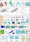
Electronic devices with engineered three-dimensional (3D) architectures are indispensable for frictional-force sensing, wide-field optical imaging, and flow velocity measurement. Recent advances in mechanically guided assembly established deterministic routes to 3D structures in high-performance materials, through controlled rolling/folding/buckling deformations. The resulting 3D structures are, however, mostly formed on planar substrates and cannot be transferred directly onto another curved substrate. Here, we introduce an ordered assembly strategy to allow transformation of 2D thin films into sophisticated 3D structures on diverse curved surfaces. The strategy leverages predefined mechanical loadings that deform curved elastomer substrates into flat/cylindrical configurations, followed by an additional uniaxial/biaxial prestretch to drive buckling-guided assembly. Release of predefined loadings results in an ordered assembly that can be accurately captured by mechanics modeling, as illustrated by dozens of complex 3D structures assembled on curved substrates. Demonstrated applications include tunable dipole antennas, flow sensors inside a tube, and integrated electronic systems capable of conformal integration with the heart.


Figures
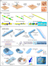
Fig. 1.
Fig. 1.. Conceptual illustration of the ordered assembly strategy of complex 3D structures on curved surfaces.
(A) Illustration of the ordered assembly strategy with the formation of a 3D decorative mask on a human face. The two images on the right correspond to the FEA prediction and optical image of 3D structures in a bilayer of Ag (5 μm) and PET (75 μm). (B) Top panel illustrates a helicoid substrate and FEA results of the helicoidal substrate that can be flattened by torsional and tensile loadings. Bottom panel presents the ordered assembly process of 3D leaf-like structures [Al (2.5 μm)/PET (30 μm)] on helicoidal substrates with FEA predictions and an optical image. (C) Conceptual illustration of the assembly of 3D structures on the inner surface of a cylindrical tube, where the substrate is cropped obliquely, flattened by bending deformations, and then prestretched, before the integration with the 2D precursor. Bottom panel presents the ordered assembly process of a hierarchical 3D helical structures [Al (2.5 μm)/PET (30 μm)] inside cylindrical tubes with FEA predictions and an optical image. (D) Illustration of the assembly process of 3D structures on a substrate with the Möbius-band shape, along with FEA predictions and optical image of ant-like structures [Al (2.5 μm)/PET (30 μm)] assembled on the substrate. Scale bars, 20 mm in (A), 10 mm in (B) and (D), and 5 mm in (C). Photo credit: Z.X. and T.J., Tsinghua University.
Fig. 2.
Fig. 2.. Assembly of complex 3D structures on curved surfaces that can be flattened.
(A) Schematic illustration of curved substrates with the horseshoe shapes, which can be flattened by uniaxial stretching. (B) Optical images that illustrate the assembly process of 3D ribbon structures on the horseshoe substrates. (C) FEA and experiment results on the generatrix profile of a hemispherical elastomer substrate under different levels of biaxial stretching. R0 denotes the radius of the initial hemisphere. (D) FEA predictions of the maximum principal strain contours in the hemispherical substrate under different levels of biaxial stretching (0, 30, 50, and 100%). (E) Comparison of straight ribbons with different length (Lribbon) assembled on the hemispherical substrate by FEA predictions. (F) 2D geometries, FEA predictions, and experimental images of various 3D structures [Cu (100 nm)/PI (8 μm) in (i) and (ii), and Al (2.5 μm)/PET (30 μm) in (iii) to (vi)] assembled on the convex and concave surfaces of hemispherical substrates. (G to J) Inverse design for a hemi-ellipsoidal surface assembled on the hemispherical substrate. (K to N) Inverse design of small hemispheres with the same height (hi) assembled at different spatial locations on the hemispherical substrate. (O and P) Optical images of a network of helical microscale structures and a tiny 3D rhomboid ribbon microscale structure assembled on a brain-like surface. Scale bars, 10 mm in (B), (F) [(iii) to (vi)], (I), and (M) and (O) (ii); 3 mm in (F) [(i) and (ii)], and (P) (left); and 500 μm in (P) (right). Photo credit: Z.X. and T.J., Tsinghua University.
Fig. 3.
Fig. 3.. Assembly of complex 3D structures on cylindrical or cylinder-like surfaces.
(A) Schematic of the aorta model used as the curved substrate, and the assembly process of helical and double-helical structures on this substrate by compressive buckling. The optical image on the rightmost corresponds to 3D structures in a bilayer of Al (2.5 μm)/PET (30 μm). (B) Assembly process of straight ribbons with different length on a cylindrical substrate by tensile buckling. θ0 denotes the central angle corresponding to a straight ribbon wrapping on the substrate along the circumferential direction. The rightmost chart presents the dimensionless maximum out-of-plane heights (Umax/R0) of different straight ribbons versus the uniaxial strain applied to the cylindrical substrate. (C) 2D geometries, FEA predictions, and experimental images of various 3D structures [(i) Cu (100 nm)/PI (8 μm); (ii to iv and vi) Al (2.5 μm)/PET (30 μm); (v) Cu (100 nm)/SU-8 (8 μm)] assembled on cylindrical substrates. Scale bars, 2 mm in (i), 10 mm in (ii) to (iv) and (vi), and 1 mm in (v). (D) 2D precursor, FEA predictions, and experimental images of kirigami-inspired scale-like 3D structures formed by tensile buckling. (E) FEA predictions and experimental images illustrate the ordered assembly process of an array of kirigami-inspired scale structures on an Archimedean spiral fiber. (F to H) Inverse design of helical structures with the same heights (h) and pitches (p) assembled at different spatial regions on the spiral fiber. Scale bars, 10 mm in (A), (D), (E), and (G). Photo credit: Z.X. and T.J., Tsinghua University.
Fig. 4.
Fig. 4.. Applicability of the assembly strategy to diverse high-performance materials and electronic devices.
(A) Optical images of various curved substrates and assembled 3D structures with a diversity of materials and length scales [(i) Si (50 nm)/PI (3 μm); (ii) indium tin oxide (ITO; 50 nm)/SU-8 (5 μm); (iii) Cu (100 nm)/PI (8 μm); (iv) laser-induced graphene (LIG) (10 μm) and PI (25 μm); (v) Al (2.5 μm)/PET (30 μm)]. Scale bars, 100 μm, 200 μm, 5 mm, 5 mm, and 10 mm (from left to right). (B to D) A highly tunable frequency-reconfigurable dipole antenna. (B) Illustration of a highly tunable dipole antenna assembled on the concave surface of a hemispherical substrate, along with FEA and experimental images of the dipole antenna [Cu (6 μm)/PI (25 μm)]. (C) Results of electromagnetic simulations and experimental measurements for the return loss (S11) as a function of the frequency for the dipole antenna under different levels of applied strains. (D) Results of electromagnetic simulations for continuous tunability resonant frequency shift as a function of applied strains. Scale bars, 5 mm. Photo credit: Z.X., T.J., and S.X., Tsinghua University.
Fig. 5.
Fig. 5.. Demonstration of 3D electronic devices that can be conformally attached onto curved surfaces of human organs.
(A to D) 3D piezoresistive flow sensor. (A) Illustration of the assembly process of a 3D piezoresistive flow sensor on the inner surface of a cylindrical tube. (B) Optical image of the fabricated device [PI (1 μm)/Cu (250 nm)/PI (25 μm)]. (C) Schematic illustration of the measurement of flow velocity. (D) Measured relative resistance changes at different flow velocities based on the 3D piezoresistive flow sensor and its 2D counterpart. (E to G) 3D integrated electronic system. (E) Schematic and optical image of a 2D integrated electronic system consisting of two commercial green LEDs, eight temperature sensors, and a humidity sensor. (F) Optical image of the assembled 3D integrated electronic system conformally wrapped onto the apex of a heart model. (G) Temperature mapping and the magnitude of relative humidity measured by the 3D device system at two different ambient conditions. Scale bars, 5 mm in (B) and 10 mm in (E) and (F). Photo credit: Z.X., T.J., and S.X., Tsinghua University.

Similar articles

Cited by

References

    1. Park Y., Chung T. S., Lee G., Rogers J. A., Materials chemistry of neural interface technologies and recent advances in three-dimensional systems. Chem. Rev. 122, 5277–5316 (2021). - PubMed
    1. Kim D.-H., Lu N., Ma R., Kim Y.-S., Kim R.-H., Wang S., Wu J., Won S. M., Tao H., Islam A., Yu K. J., Kim T.-i., Chowdhury R., Ying M., Xu L., Li M., Chung H.-J., Keum H., McCormick M., Liu P., Zhang Y.-W., Omenetto F. G., Huang Y., Coleman T., Rogers J. A., Epidermal electronics. Science 333, 838–843 (2011). - PubMed
    1. Byun S. H., Sim J. Y., Agno K. C., Jeong J. W., Materials and manufacturing strategies for mechanically transformative electronics. Mater. Today Adv. 7, 100089 (2020).
    1. Yu Y., Nyein H. Y. Y., Gao W., Javey A., Flexible electronics: Flexible electrochemical bioelectronics: The rise of in situ bioanalysis (Adv. Mater. 15/2020). Adv. Mater. 32, 2070115 (2020). - PubMed
    1. Lee Y., Bandari V. K., Li Z., Medina-Sánchez M., Maitz M. F., Karnaushenko D., Tsurkan M. V., Karnaushenko D. D., Schmidt O. G., Nano-biosupercapacitors enable autarkic sensor operation in blood. Nat. Commun. 12, 4967 (2021). - PMC - PubMed