. 2022 Aug 10;13(1):4704.
doi: 10.1038/s41467-022-32421-x.

Evidence for a HURP/EB free mixed-nucleotide zone in kinetochore-microtubules

Affiliations

Evidence for a HURP/EB free mixed-nucleotide zone in kinetochore-microtubules

Cédric Castrogiovanni et al. Nat Commun. .

Abstract

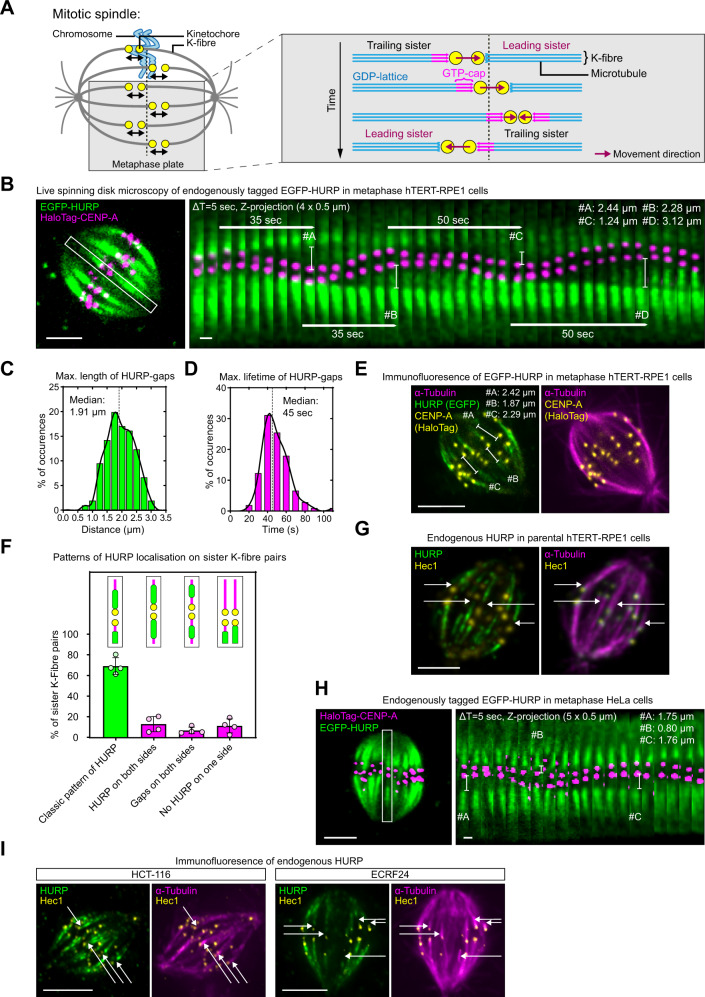
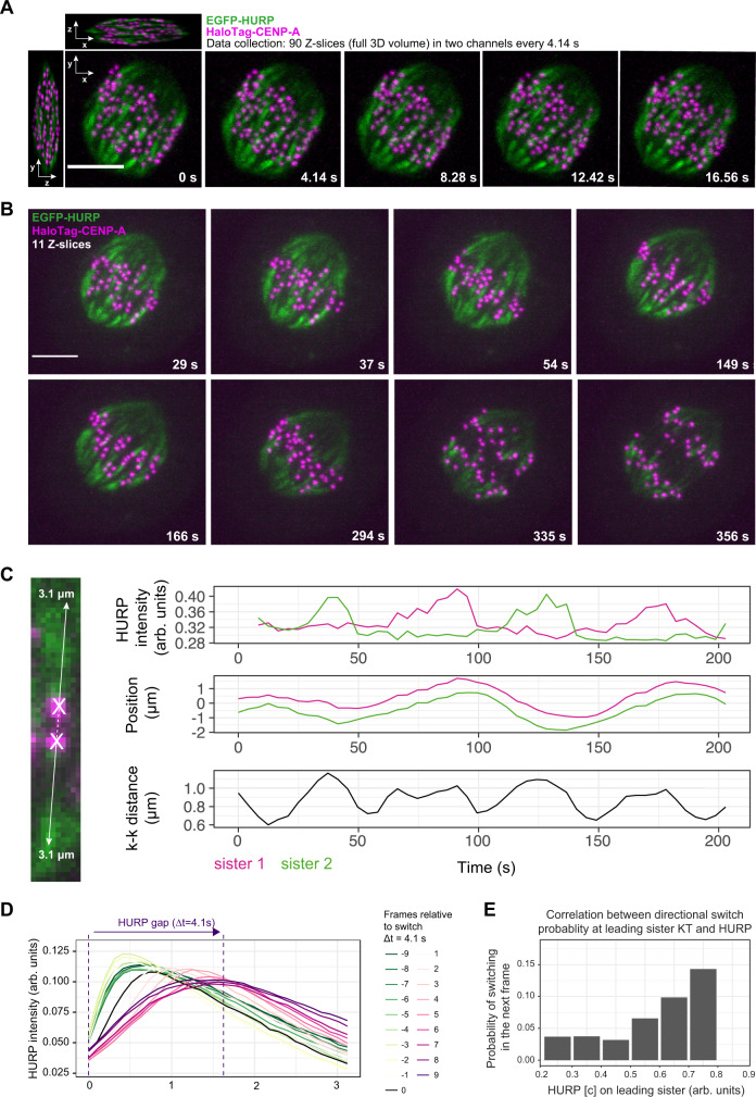
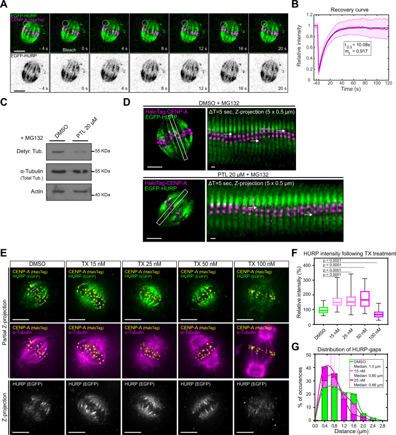
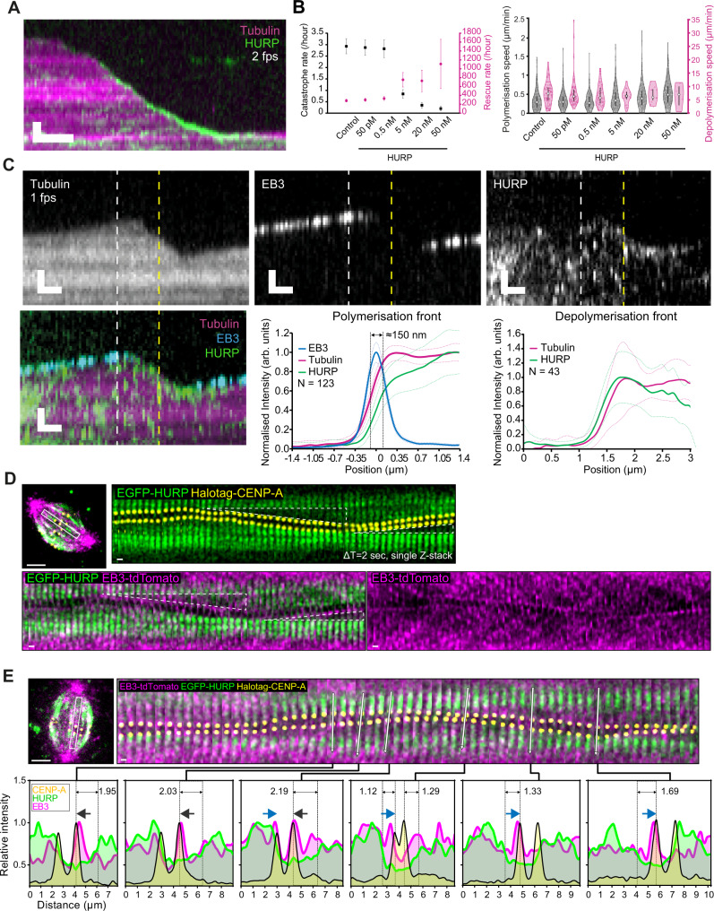
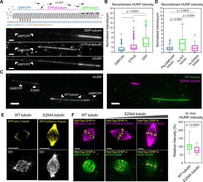
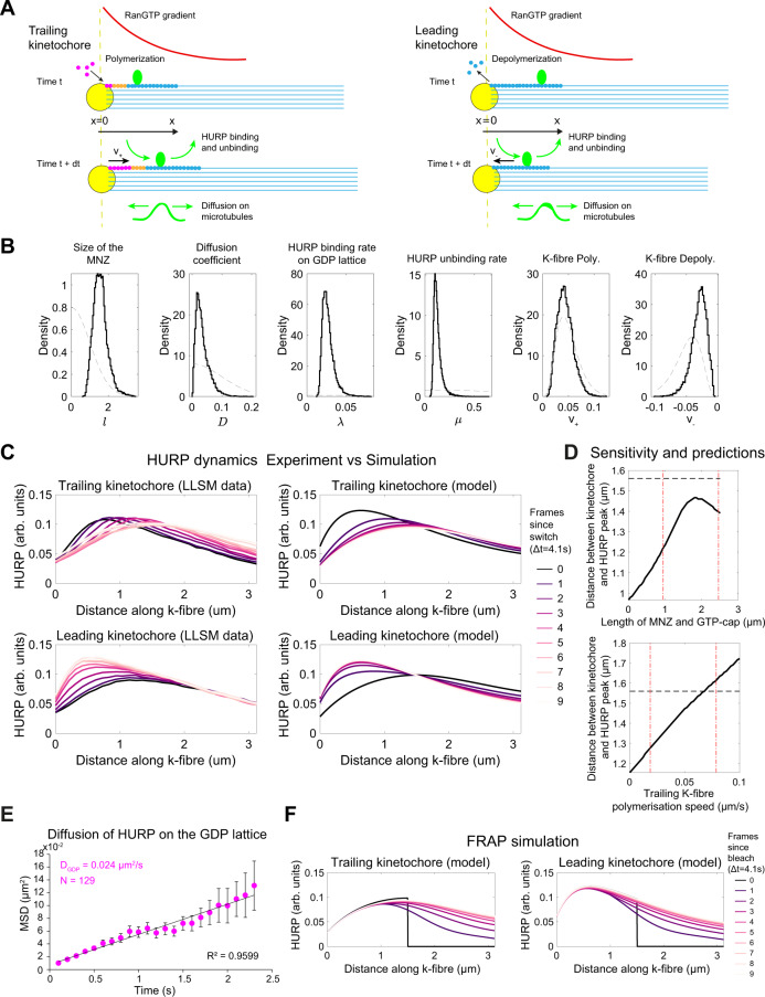
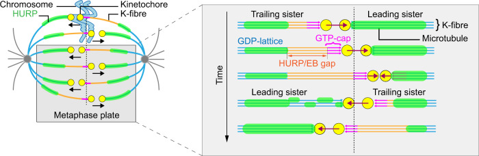
Current models infer that the microtubule-based mitotic spindle is built from GDP-tubulin with small GTP caps at microtubule plus-ends, including those that attach to kinetochores, forming the kinetochore-fibres. Here we reveal that kinetochore-fibres additionally contain a dynamic mixed-nucleotide zone that reaches several microns in length. This zone becomes visible in cells expressing fluorescently labelled end-binding proteins, a known marker for GTP-tubulin, and endogenously-labelled HURP - a protein which we show to preferentially bind the GDP microtubule lattice in vitro and in vivo. We find that in mitotic cells HURP accumulates on the kinetochore-proximal region of depolymerising kinetochore-fibres, whilst avoiding recruitment to nascent polymerising K-fibres, giving rise to a growing "HURP-gap". The absence of end-binding proteins in the HURP-gaps leads us to postulate that they reflect a mixed-nucleotide zone. We generate a minimal quantitative model based on the preferential binding of HURP to GDP-tubulin to show that such a mixed-nucleotide zone is sufficient to recapitulate the observed in vivo dynamics of HURP-gaps.


Conflict of interest statement

The authors declare no competing interests.

Figures

Fig. 1
Fig. 1. HURP is excluded from the K-fibre growth zone.
A Current model for sister-kinetochore oscillations in metaphase. B Live-cell imaging of metaphase hTERT-RPE1 EGFP-HURP/HaloTag-CENP-A cell. Inset shows sister K-fibre pair used for kymograph (right panel), bars display the HURP-gaps maximum length. C, D Distribution of live HURP-gap maximum lengths (C) and duration (D N = 4 independent experiments, n = 106 K-fibres in 29 cells) Black line = curve fit. E Immunofluorescence image of metaphase hTERT-RPE1 EGFP-HURP/HaloTag-CENP-A cell. Z-projection of 1 µm thickness. Bars show gap distances. F Quantification of mean HURP localisation patterns along sister K-fibre pairs in fixed cells. Data are presented as mean values ± SD (N = 4, n = 419 sister K-fibres in 19 cells). G Immunofluorescence image of endogenous HURP in metaphase hTERT-RPE1 cell. Z-projection of 0.5-µm thickness. Arrows indicate HURP-gaps. H Live-cell image of endogenously tagged EGFP-HURP in metaphase HeLa cell overexpressing HaloTag-CENP-A. Inset shows sister K-fibre pair used for kymograph (right panel), bars display gap maximum distances. I Immunofluorescence images of endogenous HURP in metaphase HCT-116 and ECRF24 cells. Z-projection of 1.5- and 1.0-µm thickness, respectively. Arrows indicate HURP-gaps. Scale bars = 5 µm and 1 µm (kymograph). Source data for all graphs are provided as a Source Data file.
Fig. 2
Fig. 2. HURP-gaps are precisely linked to K-fibre growth state.
A Lattice light-sheet 3D representation (X-, Y- and Z-projections) of a metaphase hTERT-RPE1-EGFP-HURP/HaloTag-CENP-A cell and relative movie stills projected in Z (90 z-slices). Scale bar = 5 µm. B Lattice light-sheet movie stills of the same cell in A projected in Z (11 z-slices). Scale bar = 5 µm. C Exemplary HURP intensities and sister-kinetochore positions in single pair over time, obtained after 3D kinetochore tracking. D Average spatial distribution of HURP along K-fibre over time relative to switch from leading to trailing (N = 3, n = 69 pairs). E Probability of directional switch in the next frame versus HURP on the K-fibre in the current frame (N = 3, n = 69 pairs). Source data for all graphs are provided as a Source Data file.
Fig. 3
Fig. 3. HURP-gaps are precisely linked to K-fibre conformation.
A FRAP time-lapse of hTERT-RPE1 EGFP-HURP/HaloTag-CENP-A cell. Inset indicates bleached region on single K-fibre. B EGFP-HURP FRAP recovery curve. Data are presented as mean values ± SD. Black line = fit of mono-exponential recovery (N = 4, n = 47 K-fibres). C Western blot analysis of detyrosinated tubulin levels in hTERT-RPE1-EGFP-HURP/HaloTag-CENP-A protein extracts of cells blocked in metaphase (10 µM MG132) and co-treated with DMSO or 20 µM Parthenolide (PTL). D Live-cell imaging of hTERT-RPE1 EGFP-HURP/HaloTag-CENP-A cell blocked in metaphase treated with DMSO or 20 µM Parthenolide (PTL). Inset shows sister K-fibre pair used for kymograph (right panel), arrows indicate the HURP-gaps. E Immunofluorescence images of metaphase hTERT-RPE1-EGFP-HURP/HaloTag-CENP-A cells treated with indicated taxol (TX) concentrations for 45 min. Partial Z-projections of 1.0, 0.8, 0.9, 1.1 and 1.3 µm thickness, respectively. Bars show HURP-gap distances. Z-projection = projection of whole spindle. F Boxplots of relative HURP intensities in taxol-treated cells as shown in E (N = 4; n = 57, 54, 65, 58 and 67 cells for DMSO, 15, 25, 50 and 100 nM, respectively). Boxplots indicate the 25th and 75th percentiles, the bars are medians, and the whiskers indicate minima and maxima; P = Kruskal–Wallis test and Dunn’s multiple comparisons. G HURP-gap size distributions in fixed metaphase hTERT-RPE1-eGFP-HURP/HaloTag-CENP-A cells treated with DMSO, or 15 and 25 nM Taxol. (N = 4; n = 272, 345 and 315 gaps for DMSO, 15 and 25 nM, respectively). Lines = curve fit. Scale bars = 5 µm and 1 µm (kymograph). Source data for all graphs are provided as a Source Data file.
Fig. 4
Fig. 4. HURP and EB3 are excluded from a micron-wide zone on growing K-fibres.
A Representative kymograph of 5 nM TagRFP-HURP binding to a dynamic microtubule; scale bar = 1 µm vertically, 10 s horizontally. B Quantification of the microtubule catastrophe and rescue rate (left) and microtubule polymerisation and depolymerisation rate (right, mean ± standard error) at different TagRFP-HURP concentrations; N = 4, 4, 3, 3, 3 experimental replicates and n = 346, 331, 264, 333, 321 and 181 microtubules analysed for control, 50 pM, 0.5, 5, 20 and 50 nM, respectively. C Representative kymographs of 5 nM TagRFP-HURP and 30 nM EB3-GFP binding to a dynamic microtubule (top, scale bar = 1 µm vertically, 10 s horizontally); mean profile of tubulin, EB3 and HURP intensities at the polymerisation and depolymerisation front (bottom, n = 123 and 43 profiles, respectively); white and yellow vertical dashed lines in the kymographs indicate the representative frame used for quantification at the polymerisation and depolymerisation front, respectively. D Representative images of HURP, CENP-A and EB3 signals in the hTERT-RPE1 EGFP-HURP/HaloTag-CENP-A cell line overexpressing EB3-tdTomato (ΔT = 2 s). Triangles highlight HURP-gaps. E Representative intensity line profiles of HURP, CENP-A and EB3 signals based on live-cell imaging of hTERT-RPE1 EGFP-HURP/HaloTag-CENP-A overexpressing EB3-tdTomato (ΔT = 2 s). White arrows indicate the selected axis of profiling. Dark grey and blue arrows show the movement direction of kinetochores. Dashed lines indicate HURP-gaps. D, E Scale bars = 5 µm and 1 µm (kymograph). Source data for all graphs are provided as a Source Data file.
Fig. 5
Fig. 5. HURP preferentially binds the GDP-lattice of microtubules.
A Schematic of barcoded porcine-tubulin microtubule with the GMPCPP-, GTPγS- and GDP-tubulin sections (top), along with corresponding fluorescence channels of GDP- (HiLyte647), GTPγS- (HiLyte488) tubulin sections (unlabelled GMPCPP-tubulin, see “Methods”) and TagRFP-HURP (bottom); scale bars = 1.5 µm. B Boxplots of the TagRFP-HURP intensity/µm normalised to its median intensity on GMPCPP microtubules (N = 3 flow chambers; n = 171 (GMPCPP), 300 (GTPγS) and 238 (GDP); P = Kruskal–Wallis test). C Representative image of porcine-tubulin GMPCPP seeds extended with either human WT- (green) or E254A tubulin (magenta), labelled with HiLyte488 and HiLyte647 porcine brain tubulin (1:7 labelled:unlabelled ratio) respectively (right panel) and incubated with TagRFP-HURP (left panel); scale bars = 3 µm. D Boxplots of HURP intensity/µm normalised to its median intensity on GMPCPP seeds (N = 3 flow chambers; n = 121 (GMPCPP), 43 (WT) and 87 (E254A tubulin); P = Kruskal–Wallis test). E Immunofluorescence images of metaphase hTERT-RPE1 cells transducted either with RFP-wt-α-tubulin or RFP-E254A-α-tubulin and stained for EB1. Scale bars = 5 µm. F Live-cell imaging of hTERT-RPE1 EGFP-HURP/HaloTag-CENP-A cells transducted either with RFP-wt-α-tubulin or RFP-E254A-α-tubulin mutant (left), Z-projections of 5 × 0.5 µm, Scale bar = 5 µm; and boxplots of in vivo relative HURP intensities (right). N = 2; n = 38 and 42 cells. Boxplots indicate the 25th and 75th percentiles, the bars are medians, and the whiskers indicate values within 1.5 times the interquartile range in B, D, and minima and maxima in F; P = two-sided Mann–Whitney test. Source data for all graphs are provided as a Source Data file.
Fig. 6
Fig. 6. A minimal computational simulation of spatiotemporal dynamics of HURP recapitulates HURP-gaps.
A Schematic showing the key components of the computational model of HURP dynamics on K-fibres, including diffusion, binding and unbinding with rates dependent on the RanGTP gradient (red) and tubulin conformation (GTP—magenta, mixed-nucleotide zone—orange, GDP—blue), and polymerisation/depolymerisation at the kinetochore resulting in the advection of HURP. B Estimated distributions of key model parameters (histograms of posterior marginal distributions) based on data from Fig. 2C (see “Methods”). Grey dashed lines indicate prior distributions (i.e., before learning from the data). C Spatiotemporal dynamics of HURP on K-fibres from in vivo data (as in Fig. 2C) and computational model predictions using fitted parameters (median of each posterior marginal distribution). D Sensitivity of the model to changes in the length of GTP-cap and mixed-nucleotide zone (top), and rate of polymerisation of the trailing K-fibre (bottom) showing how these affect the size of the HURP-gap. Other parameters remain fixed at posterior median values. Vertical dashed red lines indicate the 95% credible region. A horizontal dashed black line shows the measured HURP-gap from lattice light-sheet data. E Plots of the mean squared displacement (MSD) of HURP over time measured from in vitro data (mean ± SEM; N = 1, n = 129 traces). F Simulated FRAP experiment using parameters estimated from data (median of each posterior marginal distribution) and assuming initially HURP was bleached from a region beyond 1.5 µm from the kinetochore (zero HURP assumed initially in this region). Source data for all graphs are provided as a Source Data file.
Fig. 7
Fig. 7. Proposed model of the mixed-nucleotide zone on K-fibres.
Based on our experimental data, we propose that K-fibres contain four distinct regions: (1) A GTP-cap (magenta) close to the trailing kinetochore, characterised by an accumulation of EB proteins; (2) a micron-sized dynamic mixed-nucleotide zone (orange) on growing K-fibres that contains neither EB proteins nor HURP; (3) the GDP microtubule lattice (blue) characterised by HURP stripes; (4) a pole-proximal region that lacks HURP due to the absence of RanGTP. Note that as soon as a directional switch occurs, HURP starts to accumulate on the leading K-fibre that previously contained HURP-gap, and an equivalent gap starts to form on the opposite, growing K-fibre.

Similar articles

Cited by

References

    1. O’Toole E, Morphew M, Richard McIntosh J. Electron tomography reveals aspects of spindle structure important for mechanical stability at metaphase. Mol. Biol. Cell. 2020;31:184–195. doi: 10.1091/mbc.E19-07-0405. - DOI - PMC - PubMed
    1. Musacchio, A. & Desai, A. A molecular view of kinetochore assembly and function. Biology6, 5 (2017). - PMC - PubMed
    1. Monda, J. K. & Cheeseman, I. M. The kinetochore-microtubule interface at a glance. J. Cell Sci. 131, jcs214577 (2018). - PMC - PubMed
    1. Prosser SL, Pelletier L. Mitotic spindle assembly in animal cells: a fine balancing act. Nat. Rev. Mol. Cell Biol. 2017;18:187–201. doi: 10.1038/nrm.2016.162. - DOI - PubMed
    1. Gudimchuk NB, McIntosh JR. Regulation of microtubule dynamics, mechanics and function through the growing tip. Nat. Rev. Mol. Cell Biol. 2021;22:777–795. doi: 10.1038/s41580-021-00399-x. - DOI - PubMed

Publication types

MeSH terms