

Dual Band MEMS Directional Acoustic Sensor for Near Resonance Operation
- PMID: 35957192
- PMCID: PMC9371106
- DOI: 10.3390/s22155635
Dual Band MEMS Directional Acoustic Sensor for Near Resonance Operation
Abstract
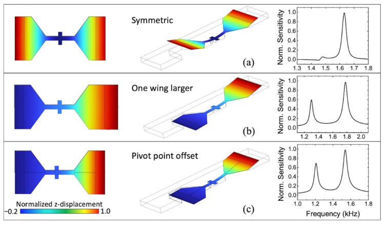
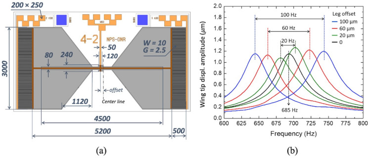
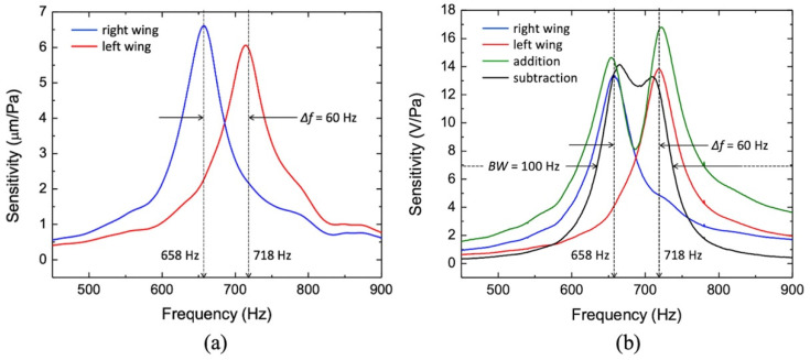
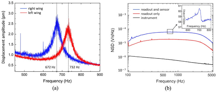
In this paper, we report on the design and characterization of a microelectromechanical systems (MEMS) directional sensor inspired by the tympana configuration of the parasitic fly Ormia ochracea. The sensor is meant to be operated at resonance and act as a natural filter for the undesirable frequency bands. By means of breaking the symmetry of a pair of coupled bridged membranes, two independent bending vibrational modes can be excited. The electronic output, obtained by the transduction of the vibration to differential capacitance and then voltage through charge amplifiers, can be manipulated to tailor the frequency response of the sensor. Four different frequency characteristics were demonstrated. The sensor exhibits, at resonance, mechanical sensitivity around 6 μm/Pa and electrical sensitivity around 13 V/Pa. The noise was thoroughly characterized, and it was found that the sensor die, rather than the fundamental vibration, induces the predominant part of the noise. The computed average signal-to-noise (SNR) ratio in the pass band is about 91 dB. This result, in combination with an accurate dipole-like directional response, indicates that this type of directional sensor can be designed to exhibit high SNR and selectable frequency responses demanded by different applications.
Keywords: MEMS sensor; acoustic sensor; bio-inspired; resonant sensors.
Conflict of interest statement
The authors declare no conflict of interest.
Figures


Similar articles
-
A Low-Frequency Multi-Band Piezoelectric MEMS Acoustic Sensor Inspired by Ormia ochracea.Micromachines (Basel). 2025 Apr 10;16(4):451. doi: 10.3390/mi16040451. Micromachines (Basel). 2025. PMID: 40283326 Free PMC article.
-
Bio-Inspired Miniature Direction Finding Acoustic Sensor.Sci Rep. 2016 Jul 21;6:29957. doi: 10.1038/srep29957. Sci Rep. 2016. PMID: 27440657 Free PMC article.
-
MEMS Underwater Directional Acoustic Sensor in Near Neutral Buoyancy Configuration.Sensors (Basel). 2022 Feb 10;22(4):1337. doi: 10.3390/s22041337. Sensors (Basel). 2022. PMID: 35214239 Free PMC article.
-
Insect-inspired acoustic micro-sensors.Curr Opin Insect Sci. 2018 Dec;30:33-38. doi: 10.1016/j.cois.2018.09.002. Epub 2018 Sep 6. Curr Opin Insect Sci. 2018. PMID: 30553482 Review.
-
Sensing Devices for Detecting and Processing Acoustic Signals in Healthcare.Biosensors (Basel). 2022 Oct 7;12(10):835. doi: 10.3390/bios12100835. Biosensors (Basel). 2022. PMID: 36290973 Free PMC article. Review.
Cited by
-
MEMS Acoustic Sensors: Charting the Path from Research to Real-World Applications.Micromachines (Basel). 2024 Dec 30;16(1):43. doi: 10.3390/mi16010043. Micromachines (Basel). 2024. PMID: 39858698 Free PMC article. Review.
-
Directional Multi-Resonant Micro-Electromechanical System Acoustic Sensor for Low Frequency Detection.Sensors (Basel). 2024 May 2;24(9):2908. doi: 10.3390/s24092908. Sensors (Basel). 2024. PMID: 38733017 Free PMC article.
-
Directional Resonant MEMS Acoustic Sensor and Associated Acoustic Vector Sensor.Sensors (Basel). 2023 Oct 1;23(19):8217. doi: 10.3390/s23198217. Sensors (Basel). 2023. PMID: 37837047 Free PMC article.
-
A Low-Frequency Multi-Band Piezoelectric MEMS Acoustic Sensor Inspired by Ormia ochracea.Micromachines (Basel). 2025 Apr 10;16(4):451. doi: 10.3390/mi16040451. Micromachines (Basel). 2025. PMID: 40283326 Free PMC article.
References
-
- Eargle J. The Microphone Book: From Mono to Stereo to Surround—A Guide to Microphone Design and Application. CRC Press; Boca Raton, FL, USA: 2012.
-
- Vakhitov S.Y. Problems of Theory and Designing for Directional Interference Microphones; Proceedings of the Audio Engineering Society Conference: 21st International Conference: Architectural Acoustics and Sound Reinforcement; St. Petersburg, Russia. 1–3 June 2002.
-
- Belcher E.O., Lynn D.C., Dinh H.Q., Laughlin T.J. Beamforming and Imaging with Acoustic Lenses in Small, High-Frequency Sonars; Proceedings of the Oceans ’99, MTS/IEEE. Riding the Crest into the 21st Century, Conference and Exhibition, Conference Proceedings (IEEE Cat. No.99CH37008); Seattle, WA, USA. 13–16 September 1999; pp. 1495–1499.
MeSH terms
Grants and funding
LinkOut - more resources
Full Text Sources
Miscellaneous
