

On-demand anchoring of wireless soft miniature robots on soft surfaces
- PMID: 35969749
- PMCID: PMC9407667
- DOI: 10.1073/pnas.2207767119
On-demand anchoring of wireless soft miniature robots on soft surfaces
Abstract
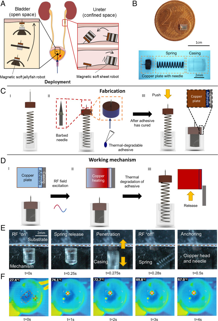
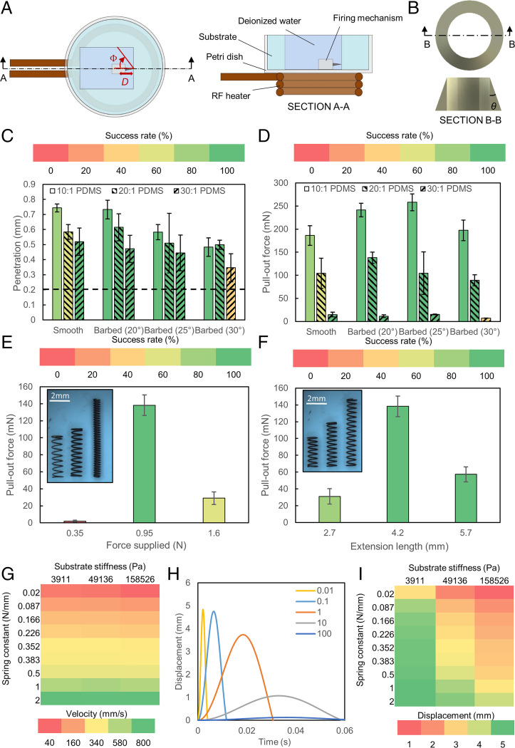
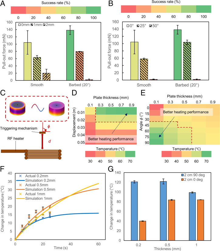
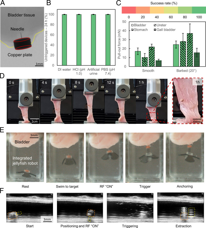
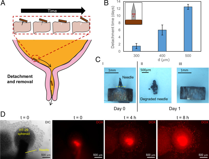
Untethered soft miniature robots capable of accessing hard-to-reach regions can enable new, disruptive, and minimally invasive medical procedures. However, once the control input is removed, these robots easily move from their target location because of the dynamic motion of body tissues or fluids, thereby restricting their use in many long-term medical applications. To overcome this, we propose a wireless spring-preloaded barbed needle release mechanism, which can provide up to 1.6 N of force to drive a barbed needle into soft tissues to allow robust on-demand anchoring on three-dimensional (3D) surfaces. The mechanism is wirelessly triggered using radio-frequency remote heating and can be easily integrated into existing untethered soft robotic platforms without sacrificing their mobility. Design guidelines aimed at maximizing anchoring over the range of the most biological tissues (kPa range) and extending the operating depth of the device inside the body (up to 75%) are also presented. Enabled by these advances, we achieve robust anchoring on a variety of ex vivo tissues and demonstrate the usage of such a device when integrated with existing soft robotic platforms and medical imaging. Moreover, by simply changing the needle, we demonstrate additional functionalities such as controlled detachment and subsurface drug delivery into 3D cancer spheroids. Given these capabilities, our proposed mechanism could enable the development of a new class of biomedical-related functionalities, such as local drug delivery, disease monitoring, and hyperthermia for future untethered soft medical robots.
Keywords: Wireless medical robots; medical devices; miniature robots; soft robots; surface anchoring.
Conflict of interest statement
The authors declare no competing interest.
Figures
Similar articles
-
Pangolin-inspired untethered magnetic robot for on-demand biomedical heating applications.Nat Commun. 2023 Jun 20;14(1):3320. doi: 10.1038/s41467-023-38689-x. Nat Commun. 2023. PMID: 37339969 Free PMC article.
-
Ultrasound-Guided Wireless Tubular Robotic Anchoring System.IEEE Robot Autom Lett. 2020 Jul;5(3):4859-4866. doi: 10.1109/LRA.2020.3003868. Epub 2020 Jun 19. IEEE Robot Autom Lett. 2020. PMID: 33880401 Free PMC article.
-
Wireless MRI-Powered Reversible Orientation-Locking Capsule Robot.Adv Sci (Weinh). 2021 Jul;8(13):2100463. doi: 10.1002/advs.202100463. Epub 2021 May 3. Adv Sci (Weinh). 2021. PMID: 35478933 Free PMC article.
-
Multicomponent and multifunctional integrated miniature soft robots.Soft Matter. 2022 Oct 12;18(39):7464-7485. doi: 10.1039/d2sm00891b. Soft Matter. 2022. PMID: 36189642 Review.
-
[Biomedical applications of bionic untethered micro-nano robots].Sheng Wu Yi Xue Gong Cheng Xue Za Zhi. 2021 Oct 25;38(5):1003-1009. doi: 10.7507/1001-5515.202006022. Sheng Wu Yi Xue Gong Cheng Xue Za Zhi. 2021. PMID: 34713669 Free PMC article. Review. Chinese.
Cited by
-
Design of Heavy-Load Soft Robots Based on a Dual Biomimetic Structure.Biomimetics (Basel). 2024 Jun 30;9(7):398. doi: 10.3390/biomimetics9070398. Biomimetics (Basel). 2024. PMID: 39056839 Free PMC article.
-
A magnetic multi-layer soft robot for on-demand targeted adhesion.Nat Commun. 2024 Jan 20;15(1):644. doi: 10.1038/s41467-024-44995-9. Nat Commun. 2024. PMID: 38245517 Free PMC article.
-
Design and fabrication of a parasite-inspired, millimeter-scale tissue anchoring mechanism.PNAS Nexus. 2024 Dec 3;3(12):pgae495. doi: 10.1093/pnasnexus/pgae495. eCollection 2024 Dec. PNAS Nexus. 2024. PMID: 39712070 Free PMC article.
-
Pangolin-inspired untethered magnetic robot for on-demand biomedical heating applications.Nat Commun. 2023 Jun 20;14(1):3320. doi: 10.1038/s41467-023-38689-x. Nat Commun. 2023. PMID: 37339969 Free PMC article.
-
Wearable and Implantable Soft Robots.Chem Rev. 2024 Oct 23;124(20):11585-11636. doi: 10.1021/acs.chemrev.4c00513. Epub 2024 Oct 11. Chem Rev. 2024. PMID: 39392765 Free PMC article. Review.
References
-
- Cianchetti M., Laschi C., Menciassi A., Dario P., Biomedical applications of soft robotics. Nat. Rev. Mater. 3, 143–153 (2018).
-
- Fusco S., et al. , An integrated microrobotic platform for on-demand, targeted therapeutic interventions. Adv. Mater. 26, 952–957 (2014). - PubMed
-
- Sitti M., Mobile Microrobotics (The MIT Press, Cambridge, MA, 2017).
-
- Kim Y., Parada G. A., Liu S., Zhao X., Ferromagnetic soft continuum robots. Sci. Robot. 4, eaax7329 (2019). - PubMed
Publication types
MeSH terms
Grants and funding
LinkOut - more resources
Full Text Sources
