. 2022 Aug 18;17(8):e0272264.
doi: 10.1371/journal.pone.0272264. eCollection 2022.

An in vitro methodology for experimental simulation on the natural hip joint

Affiliations

An in vitro methodology for experimental simulation on the natural hip joint

David Jimenez-Cruz et al. PLoS One. .

Abstract

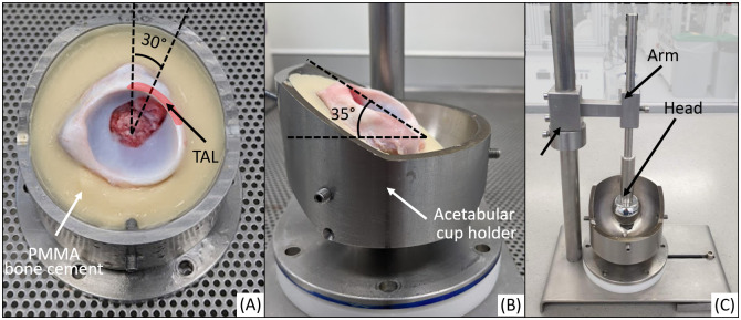
Different hip pathologies can cause geometric variation of the acetabulum and femoral head. These variations have been considered as an underlying mechanism that affects the tribology of the natural hip joint and changes the stress distribution on the articular surface, potentially leading to joint degradation. To improve understanding of the damage mechanisms and abnormal mechanics of the hip joint, a reliable in-vitro methodology that represents the in vivo mechanical environment is needed where the position of the joint, the congruency of the bones and the loading and motion conditions are clinically relevant and can be modified in a controlled environment. An in vitro simulation methodology was developed and used to assess the effect of loading on a natural hip joint. Porcine hips were dissected and mounted in a single station hip simulator and tested under different loading scenarios. The loading and motion cycle consisted of a simplified gait cycle and three peak axial loading conditions were assessed (Normal, Overload and Overload Plus). Joints were lubricated with Ringer's solution and tests were conducted for 4 hours. Photographs were taken and compared to characterise cartilage surface and labral tissue pre, during and post simulation. The results showed no evidence of damage to samples tested under normal loading conditions, whereas the samples tested under overload and overload plus conditions exhibited different severities of tears and detachment of the labrum at the antero-superior region. The location and severity of damage was consistent for samples tested under the same conditions; supporting the use of this methodology to investigate further effects of altered loading and motion on natural tissue.


Conflict of interest statement

The authors have declared that no competing interests exist.

Figures

Fig 1
Fig 1. Neutral position of the porcine hip joint in vivo.
During dissection, the landmarks (red) when viewed from the inferior direction were aligned. Landmarks were used to maintain the alignment of the bones during cementing and mounting. TAL is the transverse acetabular ligament.
Fig 2
Fig 2. Preparation of porcine hip joint.
(A) Removal of the grater trochanter and cut on the femoral diaphysis. Posterior view of the proximal femur indicating the resection of the greater trochanter and the positon for the transversal cut on the femoral shaft. (B) Resection of the pelvic bones. Lateral, anterior and posterior views indicating the three periacetabular cuts executed at approximately 15 mm from the acetabular rim.
Fig 3
Fig 3. Preparation of porcine samples for experimental simulation.
(A) Measurement of femoral head diameter with the circular templates, diameter was recorded at parallel to the epiphyseal line (growth plate) whereby at this point the head easily fitted through a template of defined size. (B) Measurement of acetabular diameters taken parallel to the TAL (ll∅); and perpendicular to TAL (⊥∅).
Fig 4
Fig 4. Overview of fixtures used for the porcine head and acetabulae for experimental simulation on the single station hip simulator (SSHS).
Centre of rotation (COR) of the simulator is indicated.
Fig 5
Fig 5. Experimental acetabular cup holder.
Inverted compared to position in Fig 4 and including a cemented porcine acetabulum showing: (A) the acetabular version angle (whereby TAL indicates the transverse acetabular ligament), (B) the acetabular inclination angle (C) acetabular height set using a metal head attached the fixture via an arm.
Fig 6
Fig 6. Experimental set up of the femoral head.
(A) Femoral head position fixed in an inverted position so it is anatomically aligned with the acetabulum using a custom potting fixture; (B) Femoral head cemented into the femoral holder (as shown in Fig 4) simulator fixture.
Fig 7
Fig 7. Simulator and mounted sample.
(A) Single station hip simulator (SSHS); (B) right porcine hip sample cemented and mounted for simulation; (C) Femoral head and acetabulum position prior simulation. FE: flexion-extension, AA: abduction-adduction; IER: interior-exterior rotation.
Fig 8
Fig 8. Loading profiles and motion for the experimental simulations.
Coloured lines show the axial loading input for the different scenarios (Green = normal load NOR; amber = overload OL and red = overload plus OL+). Black dotted lines show the motion profiles followed during all the simulations. Inset bar charts show the relative peak load in ISO 14242 axial loading and the scaled loading used in this study.
Fig 9
Fig 9. Sample photogrammetry of porcine acetabulum.
(A) Wide lens photographs show the positioning of the sample and its overall condition prior to simulation. (B) Macro lens photograph shows the condition of the tissue in more detail. Images show examples of damage present after an OL+ simulation for 14,400 cycles. (B1) Cartilage blushing. (B2) Labral tear and separation of the chondrolabral junction.
Fig 10
Fig 10. Photogrammetry of the acetabulum.
Example images demonstrating (A) pre- and (B) post-test appearance of the samples for testing under normal (NOR) conditions.
Fig 11
Fig 11. Types of acetabular damage observed following during simulations.
(A) Cartilage blushing, (B) Labral tear, (C) Large labral tear, (D) Initial chondrolabral junction separation, (E) Large labral tear and chondrolabral junction separation.
Fig 12
Fig 12. Acetabular damage assessment.
Summary of the damage presented for the different loading scenarios.

Similar articles

Cited by

References

    1. Kloppenburg M, Berenbaum F. Osteoarthritis year in review 2019: epidemiology and therapy. Osteoarthr Cartil. 2020;28(3):242–8. doi: 10.1016/j.joca.2020.01.002 - DOI - PubMed
    1. Spitaels D, Mamouris P, Vaes B, Smeets M, Luyten F, Hermens R, et al.. Epidemiology of knee osteoarthritis in general practice: a registry-based study. BMJ Open. 2020;10(1):1–9. doi: 10.1136/bmjopen-2019-031734 - DOI - PMC - PubMed
    1. Hoaglund FT, Steinbach LS. Primary osteoarthritis of the hip: etiology and epidemiology. J Am Acad Orthop Surg. 2001;9(5):320–7. doi: 10.5435/00124635-200109000-00005 - DOI - PubMed
    1. Anderson AE, Ellis BJ, Maas SA, Peters CL, Weiss JA. Validation of finite element predictions of cartilage contact pressure in the human hip joint. J Biomech Eng. 2008;130(5):1–10. doi: 10.1115/1.2953472 - DOI - PMC - PubMed
    1. Van Houcke J, Audenaert EA, Atkins PR, Anderson AE. A Combined Geometric Morphometric and Discrete Element Modeling Approach for Hip Cartilage Contact Mechanics. Front Bioeng Biotechnol. 2020;8(April):1–13. doi: 10.3389/fbioe.2020.00318 - DOI - PMC - PubMed

Publication types