. 2022 Sep;17(9):1015-1022.
doi: 10.1038/s41565-022-01189-y. Epub 2022 Aug 22.

Remotely controlled near-infrared-triggered photothermal treatment of brain tumours in freely behaving mice using gold nanostars

Affiliations

Remotely controlled near-infrared-triggered photothermal treatment of brain tumours in freely behaving mice using gold nanostars

Hamed Arami et al. Nat Nanotechnol. 2022 Sep.

Abstract

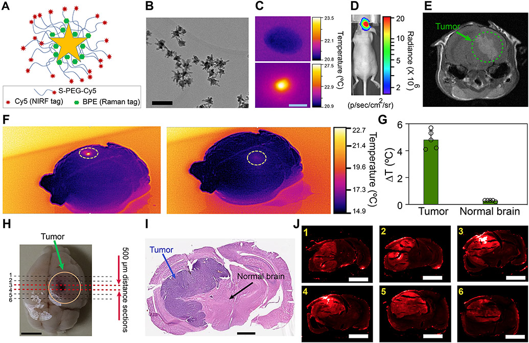
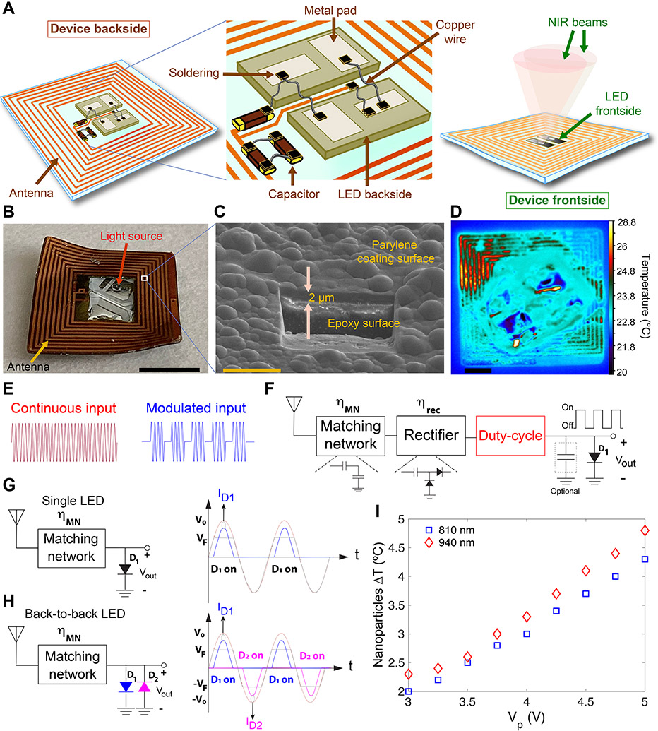
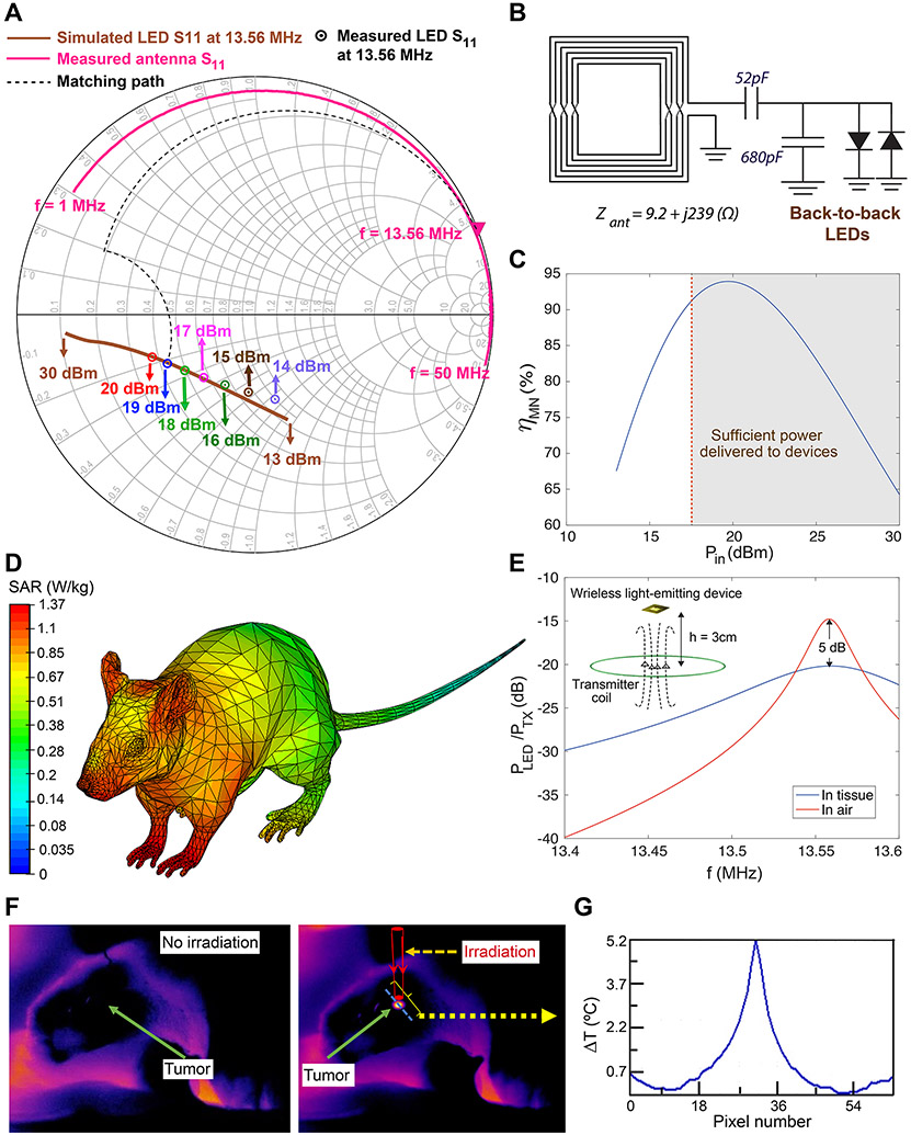
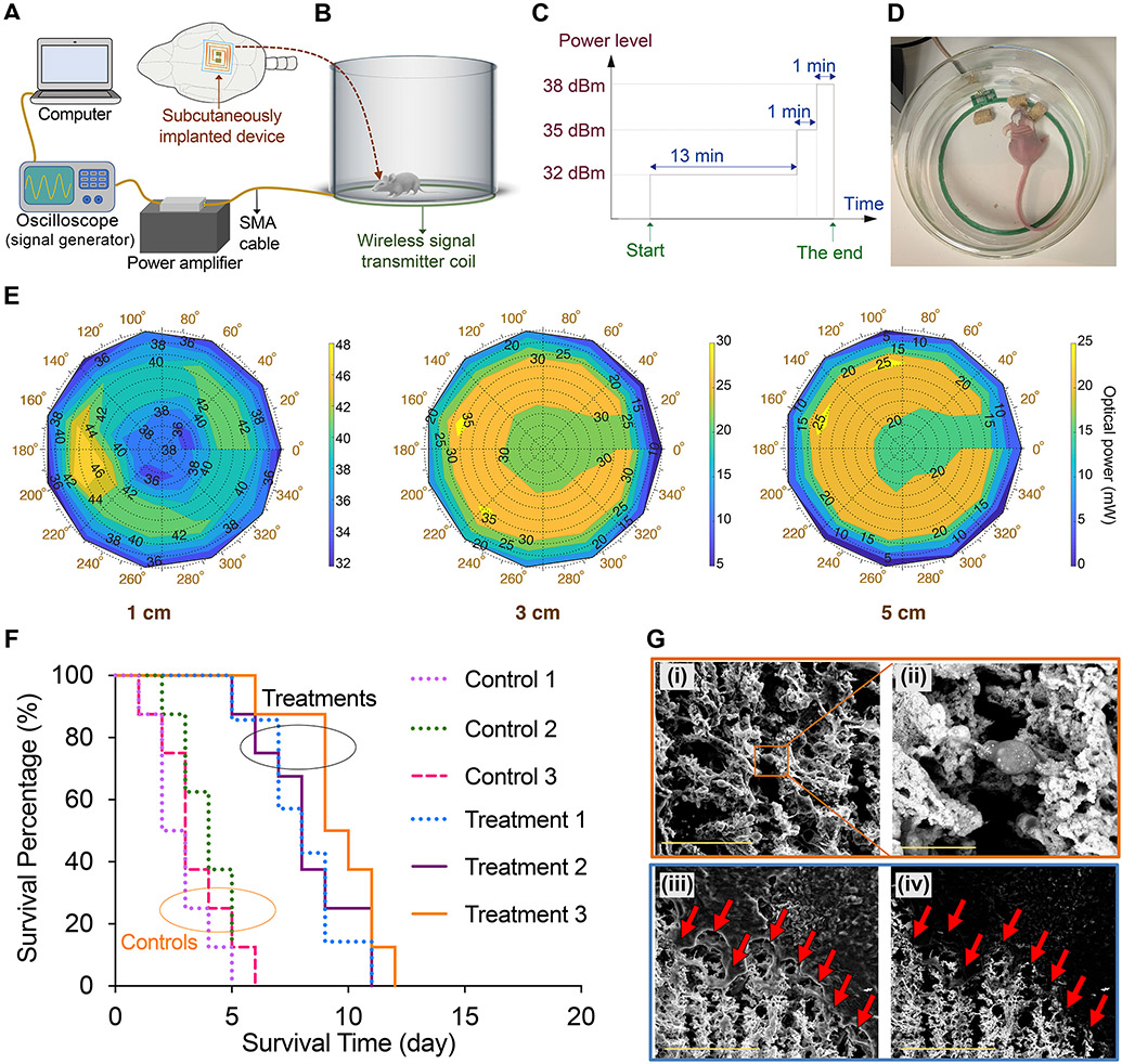
Current clinical brain tumour therapy practices are based on tumour resection and post-operative chemotherapy or X-ray radiation. Resection requires technically challenging open-skull surgeries that can lead to major neurological deficits and, in some cases, death. Treatments with X-ray and chemotherapy, on the other hand, cause major side-effects such as damage to surrounding normal brain tissues and other organs. Here we report the development of an integrated nanomedicine-bioelectronics brain-machine interface that enables continuous and on-demand treatment of brain tumours, without open-skull surgery and toxicological side-effects on other organs. Near-infrared surface plasmon characteristics of our gold nanostars enabled the precise treatment of deep brain tumours in freely behaving mice. Moreover, the nanostars' surface coating enabled their selective diffusion in tumour tissues after intratumoral administration, leading to the exclusive heating of tumours for treatment. This versatile remotely controlled and wireless method allows the adjustment of nanoparticles' photothermal strength, as well as power and wavelength of the therapeutic light, to target tumours in different anatomical locations within the brain.


Figures

Fig. 1.
Fig. 1.. Nanoparticles design for photothermal heating of the brain tumors.
(A) Schematic showing chemical conjugation of Cy5-labelled polyethylene glycol (Cy5-PEG) to the surface of nanoparticles tagged with BPE Raman reporter molecules. (B) Transmission electron microscopy demonstrating the star-shaped morphology of the nanoparticles for efficient photothermal heating in NIR range (scale bar: 100 nm). (C) Thermal image showing photothermal response of the nanoparticles under NIR irradiation (scale bar: 2 mm). (D and E) Bioluminescent imaging and T1-weighted MRI (post-Gd contrast) used to estimate tumor size (human U87-eGFP-fLuc glioblastoma) prior to injection of nanoparticles. (F) Thermal images of an excised brain. NIR-triggered heating was only observed in tumor areas injected with nanoparticles (left), without any noticeable heating effect in normal brain areas (right). (G) Quantitative analysis of the thermal images showed significant difference in temperature variation within the tumor and normal brain areas (mean±s.d., n= 5, two-sided student’s t-test, p = 0.0001). (H) Photograph of an excised brain showing sectioning locations in the tumor areas to collect 6 consecutive brain slices for histology and fluorescent microscopy analysis (scale bar: 2 mm). (I) Histological analysis of an H&E stained tissue slice showing the tumor areas (scale bar: 1 mm). (J) Fluorescent imaging of the brain slices prepared in (H) (scale bars: 2 mm). Comparisons with counterpart histological analysis tissues verified that nanoparticles were only diffused into tumors (see control image in Supplementary Fig. 5).
Fig. 2.
Fig. 2.. Designing duty-cycled NIR-emitting devices for remotely-controlled triggering of nanoparticles photothermal effect in the brain over a long-term (15 days) treatment cycle.
(A) Schematics showing the backside and frontside views of the device, and circuit design and components used for their fabrication. Flexibility of the device enables its curvilinear fitting on the mouse skull. (B and C) Representative photograph of a device (scale bar: 3 mm) and scanning electron microscopy at a selected point on the surface of the device showing a 2-μm thick parylene polymer coating (scale bar: 10 μm; also see Supplementary Fig. 15). (D) Thermal image of a device with received power of 19 dBm at the RX coil (λ = 810 nm emission, resulting in ~3 °C temperature difference in a droplet of nanoparticles) (scale bar: 1 mm). (E and F) Conventional approach for wireless powering of the LEDs integrating a matching network, a rectifier, and an optional energy storage capacitor along with a circuit which programs the duty-cycle of the LED. The duty-cycle can be adjusted by employing a switch which allows for a programmable duty-cycle generation (red box) using a continuous input or by modulating the incoming RF signal (red and blue waveforms in (E)). The definition and values of the device power efficiencies are provided in Supplementary Text. (G) Single and (H) back-to-back LED circuit designs used for wireless activation of nanoparticles’ photothermal effect. In single LED design, the LED was only ON for half the cycle, achieving a maximum duty cycle of 31.8%. However, in the back-to-back LED topology, each LED was turned on for half the cycle, and therefore at least one LED was ON during each half-cycle. This effectively doubles the duty-cycle. (I) Evaluation of nanoparticles’ heating effect during irradiations with 810-nm and 940-nm devices. Graph shows variations of nanoparticles’ ΔT with voltage amplitude (peak voltage, Vp) with a sinusoidal input. A peak voltage of around 4 V (~ 80 mW input power) resulted in ~3 °C temperature difference in a droplet of nanoparticles deposited on top of a coverslip, due to their photothermal response. TEM analysis of the nanostars (Supplementary Fig. 8) shows their morphological stability after 15 min photothermal activation for 15 consecutive days, verifying that duty-cycled irradiation of the nanoparticles with our back-to-back LED design helped to maintain the morphology of the nanoparticles and is suitable for long-term and consistent photothermal heating in the brain.
Fig. 3.
Fig. 3.. Tuning wireless power transfer efficiency and evaluating safety for photothermal therapy in freely-behaving mice.
(A) Smith chart showing simulated and measured S11 for back-to-back devices with LEDs emitting 810 nm wavelength light. The measured S11 of the antenna is also shown along with the ideal matching path (dashed line). (B) L-match structure and matching components for the back-to-back devices. The 52 pF capacitance was constructed by placing two 22 pF and 30 pF capacitors in parallel. (C) Variation of the matching network efficiency, ηMN, with input power (Pin), assuming capacitor quality factor of Qc=100 for the matching components. (D) Quantitative evaluation of mouse body interactions with 13.56 MHz RF waves to evaluate safety of the wireless power transfer in our approach during wireless therapy cycles (compare with SAR values calculated for conventional 915 MHz RF waves in Supplementary Fig. 20). The scale bar is logarithmic. (E) Effect of the tissue on the wireless link efficiency (ratio of the power received at the input of the devices to the transmitted power) after implantation on the mouse skull, suggesting ~ 5 dB degradation in the power delivered to the RX antenna, due to the tissue interaction. (F) In vivo open-skull thermal images of the brain tumor, 24 h after intratumoral injection of nanoparticles. NIR emitting device was fixed above the brain (also see Supplementary Figs. 22-23). (G) Temperature variation along the blue dotted line on the brain shown in (F), verifying that only the tumor area which contained the nanoparticles was heated during the NIR irradiation (~30 mW), due to the nanoparticles photothermal response. We did not observe any elevated temperature in surrounding normal brain tissues.
Fig. 4.
Fig. 4.. Wireless photothermal therapy of brain tumors in freely-behaving mice.
(A and B) Schematic showing the computer-controlled wireless power delivery setup used for photothermal therapy of brain tumors. (C) Multi-level powering scheme used for continuous therapy on a daily basis for 940-nm devices (see Supplementary Figs. 24 and 30 for details). (D) Photograph showing a mouse eating during the wireless tumor therapy session, indicating that our approach did not disturb animal’s normal behavior (also see Supplementary Fig. 25 and Supplementary Video 1). (E) Plots showing optical power versus the polar position of the NIR-emitting devices (940 nm, pre-implantation) from the center of the wireless transmitter (TX) coil to evaluate variations of the optical power with height changes to account for movement of the mice. Also, see Supplementary Figs. 26-28 for measurement setup and other related plots for both 810- and 940-nm devices. (F) Survival profiles of the mice with human U87-eGFP-fLuc glioblastoma tumors treated with wireless photothermal approach (Treatment groups 1, 2, and 3) compared with control mice (n=10/group, total=60). NPs (1 μL, 0.5 nM) were injected intratumorally, and photothermal therapy was started after 24 h (15 min per day for 15 days). [Control 1: NPs (−), Implantation (−); Control 2: NPs (+), Microfiber (+), Irradiation (−); Control 3: NPs (+), Device (+), Irradiation (−); Treatment 1: NPs (+), Microfiber (+), Irradiation [810 nm] (+); Treatment 2: NPs (+), 810 nm Device (+), Irradiation (+); Treatment 3: NPs (+), 940 nm Device (+), Irradiation (+)]. Significant differences were observed when comparing each treatment group with control profiles (p<0.05, using the log-rank test). Also see survival results for mice with GL26 and GBM39 tumors, as well as combination therapy results in Supplementary Figs. 41-43. (G) Secondary electron (i and iii) and backscattered (ii and iv) SEM images of a brain section, showing photothermal effect of the nanoparticles (porous areas shown with arrows) in tumor tissue. All bright contrast spots in backscattered images (ii and iv) represent gold nanoparticles due to their enhanced electron backscattering (see Supplementary Figs. 44-48 for more detailed histological analysis of the tumors at the end of therapies). Scale bars in (i), (ii), and (iii-iv) represent 50, 10, and 100 μm, respectively.

Comment in

  • Wireless nanomedicine for brain tumors.
    Ho JS, Zhang Y. Ho JS, et al. Nat Nanotechnol. 2022 Sep;17(9):907-908. doi: 10.1038/s41565-022-01188-z. Nat Nanotechnol. 2022. PMID: 35995856 No abstract available.

References

    1. Ostrom QT et al. CBTRUS Statistical Report: Primary Brain and Other Central Nervous System Tumors Diagnosed in the United States in 2013-2017. Neuro Oncol 22, iv1–iv96, doi:10.1093/neuonc/noaa200 (2020). - DOI - PMC - PubMed
    1. Stupp R et al. Effect of Tumor-Treating Fields Plus Maintenance Temozolomide vs Maintenance Temozolomide Alone on Survival in Patients With Glioblastoma: A Randomized Clinical Trial. JAMA 318, 2306–2316, doi:10.1001/jama.2017.18718 (2017). - DOI - PMC - PubMed
    1. Kok HP et al. Heating technology for malignant tumors: a review. Int J Hyperthermia 37, 711–741, doi:10.1080/02656736.2020.1779357 (2020). - DOI - PMC - PubMed
    1. Bastiancich C, Da Silva A & Esteve MA Photothermal Therapy for the Treatment of Glioblastoma: Potential and Preclinical Challenges. Front Oncol 10, 610356, doi:10.3389/fonc.2020.610356 (2020). - DOI - PMC - PubMed
    1. Pinto A & Pocard M Photodynamic therapy and photothermal therapy for the treatment of peritoneal metastasis: a systematic review. Pleura Peritoneum 3, 20180124, doi:10.1515/pp-2018-0124 (2018). - DOI - PMC - PubMed

Publication types