

Deterministic Terahertz Wave Control in Scattering Media
- PMID: 35996370
- PMCID: PMC9389618
- DOI: 10.1021/acsphotonics.2c00061
Deterministic Terahertz Wave Control in Scattering Media
Abstract
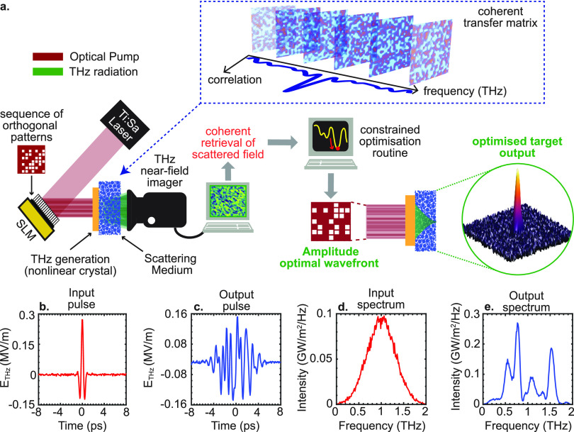
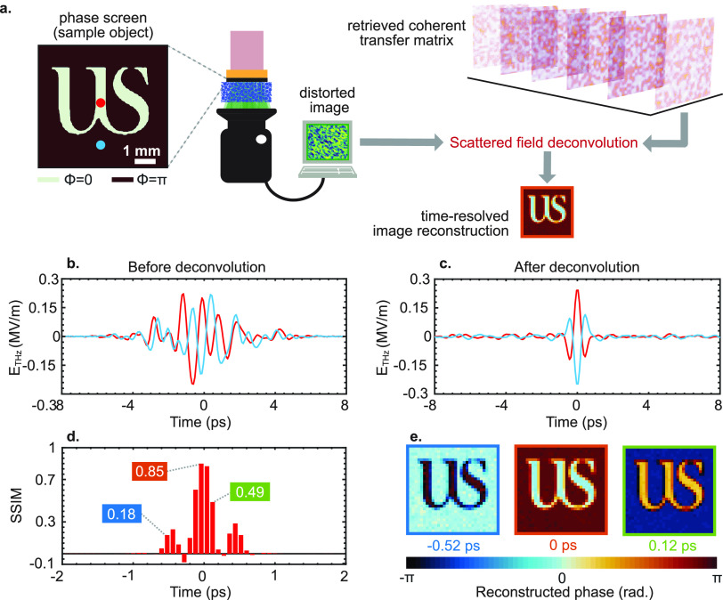
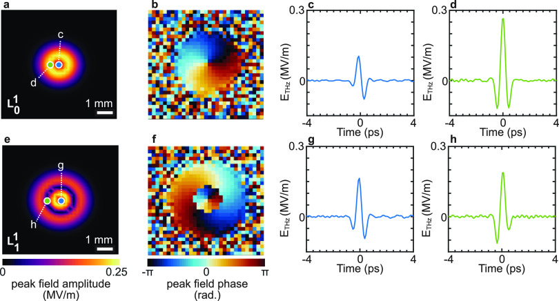
Scattering-assisted synthesis of broadband optical pulses is recognized to have a cross-disciplinary fundamental and application importance. Achieving full-waveform synthesis generally requires means for assessing the instantaneous electric field, i.e., the absolute electromagnetic phase. These are generally not accessible to established methodologies for scattering-assisted pulse envelope and phase shaping. The lack of field sensitivity also results in complex indirect approaches to evaluate the scattering space-time properties. The terahertz frequency domain potentially offers some distinctive new possibilities, thanks to the availability of methods to perform absolute measurements of the scattered electric field, as opposed to optical intensity-based diagnostics. An interesting conceptual question is whether this additional degree of freedom can lead to different types of methodologies toward wave shaping and direct field-waveform control. In this work, we theoretically investigate a deterministic scheme to achieve broadband, spatiotemporal waveform control of terahertz fields mediated by a scattering medium. Direct field access via time-domain spectroscopy enables a process in which the field and scattering matrix of the medium are assessed with minimal experimental efforts. Then, illumination conditions for an arbitrary targeted output field waveform are deterministically retrieved through numerical inversion. In addition, complete field knowledge enables reconstructing field distributions with complex phase profiles, as in the case of phase-only masks and optical vortices, a significantly challenging task for traditional implementations at optical frequencies based on intensity measurements aided with interferometric techniques.
© 2022 The Authors. Published by American Chemical Society.
Conflict of interest statement
The authors declare no competing financial interest.
Figures
Similar articles
-
Terahertz Spatiotemporal Wave Synthesis in Random Systems.ACS Photonics. 2024 Jan 9;11(2):362-368. doi: 10.1021/acsphotonics.3c01671. eCollection 2024 Feb 21. ACS Photonics. 2024. PMID: 38405391 Free PMC article.
-
Terahertz microscopy through complex media.Sci Rep. 2025 Apr 5;15(1):11706. doi: 10.1038/s41598-025-95951-6. Sci Rep. 2025. PMID: 40188248 Free PMC article.
-
Nonlinear field-control of terahertz waves in random media for spatiotemporal focusing.Open Res Eur. 2023 Feb 13;2:32. doi: 10.12688/openreseurope.14508.3. eCollection 2022. Open Res Eur. 2023. PMID: 37645307 Free PMC article.
-
Wavefront shaping: A versatile tool to conquer multiple scattering in multidisciplinary fields.Innovation (Camb). 2022 Aug 2;3(5):100292. doi: 10.1016/j.xinn.2022.100292. eCollection 2022 Sep 13. Innovation (Camb). 2022. PMID: 36032195 Free PMC article. Review.
-
Electric field-induced effects on neuronal cell biology accompanying dielectrophoretic trapping.Adv Anat Embryol Cell Biol. 2003;173:III-IX, 1-77. doi: 10.1007/978-3-642-55469-8. Adv Anat Embryol Cell Biol. 2003. PMID: 12901336 Review.
Cited by
-
Terahertz Spatiotemporal Wave Synthesis in Random Systems.ACS Photonics. 2024 Jan 9;11(2):362-368. doi: 10.1021/acsphotonics.3c01671. eCollection 2024 Feb 21. ACS Photonics. 2024. PMID: 38405391 Free PMC article.
-
Terahertz Nonlinear Ghost Imaging via Plane Decomposition: Toward Near-Field Micro-Volumetry.ACS Photonics. 2023 Mar 10;10(6):1726-1734. doi: 10.1021/acsphotonics.2c01727. eCollection 2023 Jun 21. ACS Photonics. 2023. PMID: 37363629 Free PMC article.
-
Single-shot polarimetry of vector beams by supervised learning.Nat Commun. 2023 Apr 1;14(1):1831. doi: 10.1038/s41467-023-37474-0. Nat Commun. 2023. PMID: 37005410 Free PMC article.
-
Terahertz microscopy through complex media.Sci Rep. 2025 Apr 5;15(1):11706. doi: 10.1038/s41598-025-95951-6. Sci Rep. 2025. PMID: 40188248 Free PMC article.
-
Self-Modulated Ghost Imaging in Dynamic Scattering Media.Sensors (Basel). 2023 Nov 6;23(21):9002. doi: 10.3390/s23219002. Sensors (Basel). 2023. PMID: 37960701 Free PMC article.
References
-
- Laser Speckle and Related Phenomena, Dainty J. C., Ed.; Topics in Applied Physics; Springer-Verlag: Berlin, Heidelberg, 1975.
-
- Sheng P.Introduction to Wave Scattering, Localization and Mesoscopic Phenomena, 2nd ed.; Springer Series in Materials Science; Springer-Verlag: Berlin, Heidelberg, 2006.
-
- Ishimaru A.Electromagnetic Wave Propagation, Radiation, and Scattering: From Fundamentals to Applications, 2nd ed.; Wiley: Hoboken, New Jersey, 2017.
-
- Wax A.; Backman V.. Biomedical Applications of Light Scattering; McGraw-Hill Education, 2010.
Associated data
LinkOut - more resources
Full Text Sources