. 2022 Aug 24;12(1):14430.
doi: 10.1038/s41598-022-18605-x.

Single-shot ptychography at a soft X-ray free-electron laser

Affiliations

Single-shot ptychography at a soft X-ray free-electron laser

Konstantin Kharitonov et al. Sci Rep. .

Abstract

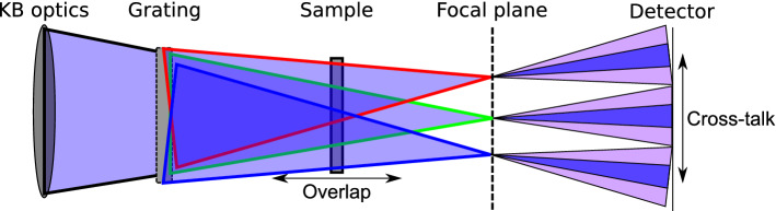
In this work, single-shot ptychography was adapted to the XUV range and, as a proof of concept, performed at the free-electron laser FLASH at DESY to obtain a high-resolution reconstruction of a test sample. Ptychography is a coherent diffraction imaging technique capable of imaging extended samples with diffraction-limited resolution. However, its scanning nature makes ptychography time-consuming and also prevents its application for mapping of dynamical processes. Single-shot ptychography can be realized by collecting the diffraction patterns of multiple overlapping beams in one shot and, in recent years, several concepts based on two con-focal lenses were employed in the visible regime. Unfortunately, this approach cannot be extended straightforwardly to X-ray wavelengths due to the use of refractive optics. Here, a novel single-shot ptychography setup utilizes a combination of X-ray focusing optics with a two-dimensional beam-splitting diffraction grating. It facilitates single-shot imaging of extended samples at X-ray wavelengths.


Conflict of interest statement

The authors declare no competing interests.

Figures

Figure 1
Figure 1
A schematic 2D diagram of the proposed experimental setup. The FEL beam is focused downstream of the sample by the pair of KB mirrors. The beam-splitting grating is placed in front of the sample and splits the beam into several diffraction orders (shown in red, green, and blue). The sample, placed in the vicinity of the grating, is illuminated by the overlapping beamlets produced by the grating. The degree of overlap and the field of view in the sample plane can be controlled by changing the grating-sample distance. The detector is placed downstream of the focal plane. The focal length of the KB mirrors is selected such that a separation of the beamlets is facilitated (dark blue) and possible cross-talk between the radiation scattered by the sample minimized (light-purple).
Figure 2
Figure 2
Schematic of the experimental setup. The FEL beam was focused 9 cm after the sample using bendable KB mirrors. The beam-splitting 2D diffraction grating was placed 210 cm after the center of the last KB mirror. The sample was placed approximately 0.9 cm behind the grating and thus illuminated by the overlapping beamlets produced by the grating. The two areas of the Siemens star sample ‘letters’ and ‘stripes’ are shown in the insets. The ANDOR iKon-M SO CCD was placed in the intermediate field 66 cm downstream of the sample. Alternatively, the PERCIVAL detector was placed in the intermediate field 135 cm downstream of the sample.
Figure 3
Figure 3
Illustration of the segmentation of the diffraction pattern. (a) Voronoi tessellation of the measured data. Centers of masses of sub-patterns corresponding to each of the grating orders are shown with green dots. Red polygons represent individual Voronoi cells fitting in the area of the detector chip. Green squares show the smallest square simultaneously circumscribed about and concentric with the largest Voronoi cell. (b) Split data used for the reconstruction. The area highlighted in yellow is inside the corresponding Voronoi cell and is constrained during the reconstruction. Each individual square is equivalent to a measurement from an individual beamlet and represents the individual computational frame used for the propagation of the respective diffraction order. The coordinates of the individual diffraction order at the sample plane can be estimated using the grating-sample distance and the grating parameters. All the data pieces with the less than half of the pixels measured were ignored during the reconstruction (right- and lower- most squares, dark in (b)). The (0, 0) order was also ignored during the reconstruction due to high levels of parasitic scattering from the beam passing through the frame of the grating.
Figure 4
Figure 4
Raw data and results of the single-shot ptychography reconstructions. (a,b) Raw data used for the reconstructions of the (c)—‘stripes’ and (d)—‘letters’ regions of the sample. (a,b) were measured using the Andor and the PERCIVAL detector respectively. (c,d) Reconstructed sample transmission for (c)—‘stripes’ and (d) ‘letters’ regions of the Siemsens star sample. (e,f) Reconstructed complex wavefields of the main probe mode corresponding to (b,c), respectively. Percentages in the lower left corner represent the occupancy of the main mode.
Figure 5
Figure 5
(a,b) Estimated resolutions of reconstructions using Fourier ring correlation, (a,b) correspond to Fig. 4 (c,d), respectively.

References

    1. Guizar-Sicairos M, Thibault P. Ptychography: A solution to the phase problem. Phys. Today. 2021;74:42–48. doi: 10.1063/PT.3.4835. - DOI
    1. Kharitonov K, et al. Flexible ptychography platform to expand the potential of imaging at free electron lasers. Opt. Express. 2021;29:22345–22365. doi: 10.1364/OE.426931. - DOI - PubMed
    1. Schropp A, et al. Full spatial characterization of a nanofocused x-ray free-electron laser beam by ptychographic imaging. Sci. Rep. 2013;3:1–5. doi: 10.1038/srep01633. - DOI - PMC - PubMed
    1. Sala S, et al. Pulse-to-pulse wavefront sensing at free-electron lasers using ptychography. J. Appl. Crystallogr. 2020;53:25. doi: 10.1107/S1600576720006913. - DOI - PMC - PubMed
    1. Sidorenko P, Cohen O. Single-shot ptychography. Optica. 2016;3:9. doi: 10.1364/OPTICA.3.000009. - DOI - PubMed