

Multi-Resin Masked Stereolithography (MSLA) 3D Printing for Rapid and Inexpensive Prototyping of Microfluidic Chips with Integrated Functional Components
- PMID: 36005047
- PMCID: PMC9405740
- DOI: 10.3390/bios12080652
Multi-Resin Masked Stereolithography (MSLA) 3D Printing for Rapid and Inexpensive Prototyping of Microfluidic Chips with Integrated Functional Components
Abstract
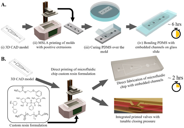
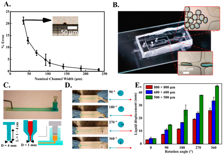
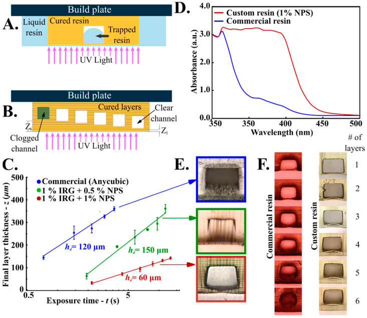
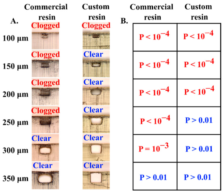
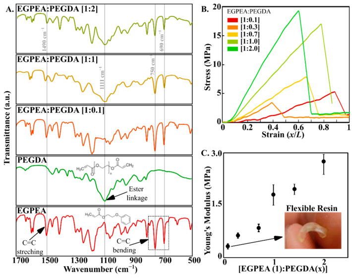
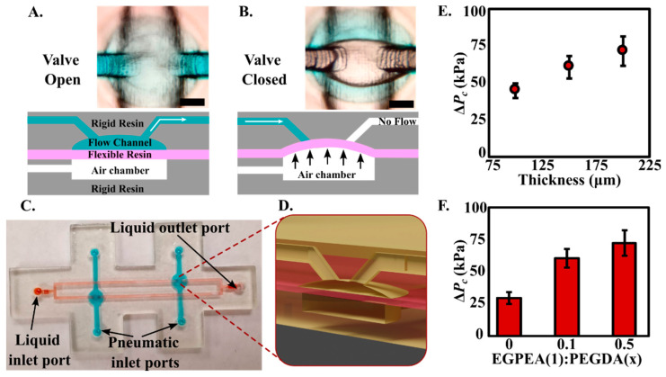
Stereolithography based 3D printing of microfluidics for prototyping has gained a lot of attention due to several advantages such as fast production, cost-effectiveness, and versatility over traditional photolithography-based microfabrication techniques. However, existing consumer focused SLA 3D printers struggle to fabricate functional microfluidic devices due to several challenges associated with micron-scale 3D printing. Here, we explore the origins and mechanism of the associated failure modes followed by presenting guidelines to overcome these challenges. The prescribed method works completely with existing consumer class inexpensive SLA printers without any modifications to reliably print PDMS cast microfluidic channels with channel sizes as low as ~75 μm and embedded channels with channel sizes as low ~200 μm. We developed a custom multi-resin formulation by incorporating Polyethylene glycol diacrylate (PEGDA) and Ethylene glycol polyether acrylate (EGPEA) as the monomer units to achieve micron sized printed features with tunable mechanical and optical properties. By incorporating multiple resins with different mechanical properties, we were able to achieve spatial control over the stiffness of the cured resin enabling us to incorporate both flexible and rigid components within a single 3D printed microfluidic chip. We demonstrate the utility of this technique by 3D printing an integrated pressure-actuated pneumatic valve (with flexible cured resin) in an otherwise rigid and clear microfluidic device that can be fabricated in a one-step process from a single CAD file. We also demonstrate the utility of this technique by integrating a fully functional finger-actuated microfluidic pump. The versatility and accessibility of the demonstrated fabrication method have the potential to reduce our reliance on expensive and time-consuming photolithographic techniques for microfluidic chip fabrication and thus drastically lowering our barrier to entry in microfluidics research.
Keywords: 3D printing; microfluidic pump; microfluidic valve; microfluidics; resin; stereolithography.
Conflict of interest statement
The authors declare no conflict of interest
Figures
Similar articles
-
Fabrication routes via projection stereolithography for 3D-printing of microfluidic geometries for nucleic acid amplification.PLoS One. 2020 Oct 28;15(10):e0240237. doi: 10.1371/journal.pone.0240237. eCollection 2020. PLoS One. 2020. PMID: 33112867 Free PMC article.
-
Advantages of stereolithographic 3D printing in the fabrication of the Affiblot device for dot-blot assays.Mikrochim Acta. 2024 Jul 2;191(8):442. doi: 10.1007/s00604-024-06512-z. Mikrochim Acta. 2024. PMID: 38954238 Free PMC article.
-
Investigation and comparison of resin materials in transparent DLP-printing for application in cell culture and organs-on-a-chip.Biomater Sci. 2022 Apr 12;10(8):1981-1994. doi: 10.1039/d1bm01794b. Biomater Sci. 2022. PMID: 35262097
-
Applied tutorial for the design and fabrication of biomicrofluidic devices by resin 3D printing.Anal Chim Acta. 2022 May 29;1209:339842. doi: 10.1016/j.aca.2022.339842. Epub 2022 Apr 30. Anal Chim Acta. 2022. PMID: 35569850 Free PMC article. Review.
-
A 'print-pause-print' protocol for 3D printing microfluidics using multimaterial stereolithography.Nat Protoc. 2023 Apr;18(4):1243-1259. doi: 10.1038/s41596-022-00792-6. Epub 2023 Jan 6. Nat Protoc. 2023. PMID: 36609643 Free PMC article. Review.
Cited by
-
Development of Biocompatible 3D-Printed Artificial Blood Vessels through Multidimensional Approaches.J Funct Biomater. 2023 Oct 8;14(10):497. doi: 10.3390/jfb14100497. J Funct Biomater. 2023. PMID: 37888162 Free PMC article. Review.
-
Customization of Computed Tomography Radio-Opacity in 3D-Printed Contrast-Injectable Tumor Phantoms.Micromachines (Basel). 2024 Jul 31;15(8):992. doi: 10.3390/mi15080992. Micromachines (Basel). 2024. PMID: 39203643 Free PMC article.
-
High-Performance Polymer-derived Ceramics in LCD 3D Printing.Adv Sci (Weinh). 2025 May;12(18):e2416176. doi: 10.1002/advs.202416176. Epub 2025 Mar 17. Adv Sci (Weinh). 2025. PMID: 40091655 Free PMC article.
-
In situ 3D polymerization (IS-3DP): Implementing an aqueous two-phase system for the formation of 3D objects inside a microfluidic channel.Biomicrofluidics. 2024 Oct 24;18(5):054113. doi: 10.1063/5.0226620. eCollection 2024 Sep. Biomicrofluidics. 2024. PMID: 39464241
-
Optimising total knee replacement imaging: a novel 3D printed PET/CT anthropomorphic phantom for metal artefact simulation.EJNMMI Phys. 2024 Mar 28;11(1):31. doi: 10.1186/s40658-024-00634-2. EJNMMI Phys. 2024. PMID: 38538815 Free PMC article.
References
-
- Convery N., Gadegaard N. 30 years of microfluidics. Micro Nano Eng. 2019;2:76–91. doi: 10.1016/j.mne.2019.01.003. - DOI
MeSH terms
Grants and funding
LinkOut - more resources
Full Text Sources
Miscellaneous
