

Bioengineering Tools Applied to Dentistry: Validation Methods for In Vitro and In Silico Analysis
- PMID: 36005243
- PMCID: PMC9406698
- DOI: 10.3390/dj10080145
Bioengineering Tools Applied to Dentistry: Validation Methods for In Vitro and In Silico Analysis
Abstract
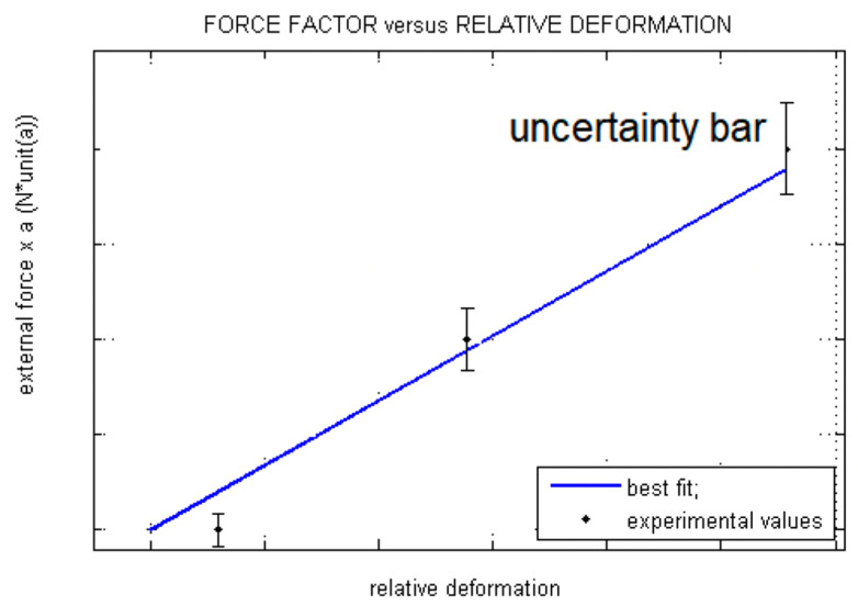
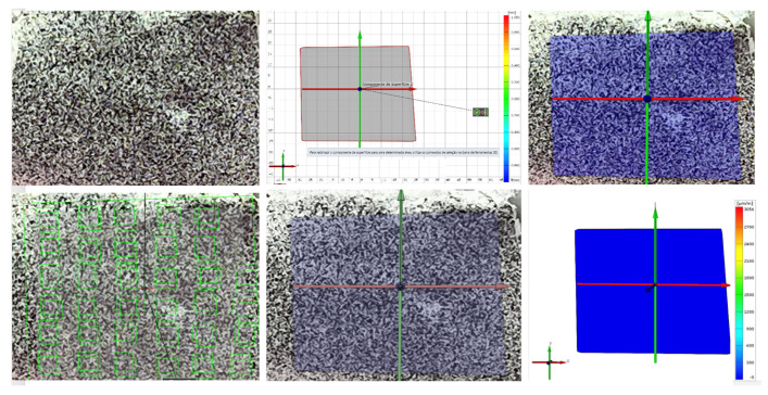
This study aimed to evaluate the use of bioengineering tools, finite element analysis, strain gauge analysis, photoelastic analysis, and digital image correlation, in computational studies with greater validity and reproducibility. A bibliographic search was performed in the main health databases PUBMED and Scholar Google, in which different studies, among them, laboratory studies, case reports, systematic reviews, and literature reviews, which were developed in living individuals, were included. Therefore, articles that did not deal with the use of finite element analysis, strain gauge analysis, photoelastic analysis, and digital image correlation were excluded, as well as their use in computational studies with greater validity and reproducibility. According to the methodological analysis, it is observed that the average publication of articles in the Pubmed database was 2.03 and with a standard deviation of 1.89. While in Google Scholar, the average was 0.78 and the standard deviation was 0.90. Thus, it is possible to verify that there was a significant variation in the number of articles in the two databases. Modern dentistry finds in finite element analysis, strain gauge, photoelastic and digital image correlation a way to analyze the biomechanical behavior in dental materials to obtain results that assist to obtain rehabilitations with favorable prognosis and patient satisfaction.
Keywords: computer simulation; computing methodologies; dentistry; finite element analysis.
Conflict of interest statement
The authors declare no conflict of interest.
Figures
Similar articles
-
Biomechanics studies in dentistry: bioengineering applied in oral implantology.J Craniofac Surg. 2009 Jul;20(4):1173-7. doi: 10.1097/SCS.0b013e3181acdb81. J Craniofac Surg. 2009. PMID: 19568186 Review.
-
Biomechanical methods applied in dentistry: a comparative overview of photoelastic examinations, strain gauge measurements, finite element analysis and three-dimensional deformation analysis.Eur J Prosthodont Restor Dent. 2009 Jun;17(2):50-7. Eur J Prosthodont Restor Dent. 2009. PMID: 19645304
-
Development and validation of risk of bias tool for the use of finite element analysis in dentistry (ROBFEAD).Comput Methods Biomech Biomed Engin. 2023 Oct-Dec;26(15):1822-1833. doi: 10.1080/10255842.2022.2148465. Epub 2022 Dec 7. Comput Methods Biomech Biomed Engin. 2023. PMID: 36475384
-
Use of stress analysis methods to evaluate the biomechanics of oral rehabilitation with implants.J Oral Implantol. 2014 Apr;40(2):217-28. doi: 10.1563/AAID-JOI-D-11-00066. J Oral Implantol. 2014. PMID: 24779954 Review.
-
Retrieving clinical evidence: a comparison of PubMed and Google Scholar for quick clinical searches.J Med Internet Res. 2013 Aug 15;15(8):e164. doi: 10.2196/jmir.2624. J Med Internet Res. 2013. PMID: 23948488 Free PMC article.
Cited by
-
Biomechanical behaviour of tilted abutment after fixed partial denture restoration of CAD/CAM materials.BMC Oral Health. 2024 Sep 27;24(1):1128. doi: 10.1186/s12903-024-04890-7. BMC Oral Health. 2024. PMID: 39334128 Free PMC article.
-
Linc-PINT downregulation of TGF-β signaling pathway in heart arrhythmia: an in silico analysis.J Diabetes Metab Disord. 2025 Apr 1;24(1):93. doi: 10.1007/s40200-025-01609-5. eCollection 2025 Jun. J Diabetes Metab Disord. 2025. PMID: 40182583
-
Influence of Abutment Design on Biomechanical Behavior to Support a Screw-Retained 3-Unit Fixed Partial Denture.Materials (Basel). 2022 Sep 8;15(18):6235. doi: 10.3390/ma15186235. Materials (Basel). 2022. PMID: 36143553 Free PMC article.
-
A Retrospect of the Special Issue "Advances in Oral Implant Health".Dent J (Basel). 2023 Mar 31;11(4):93. doi: 10.3390/dj11040093. Dent J (Basel). 2023. PMID: 37185471 Free PMC article.
-
Effect of Crestal Position on Bone-Implant Stress Interface of Three-Implant Splinted Prostheses: A Finite Element Analysis.Materials (Basel). 2025 Jul 16;18(14):3344. doi: 10.3390/ma18143344. Materials (Basel). 2025. PMID: 40731554 Free PMC article.
References
-
- Soares C.J., Raposo L.H., Soares P.V., Santos-Filho P.C., Menezes M.S., Soares P.B., Magalhães D. Effect of different types of cement on the biomechanical behavior of teeth restored with cast dowel-and-cores-in Vitro and FEA analysis. J. Prosthodont. 2010;19:130–137. doi: 10.1111/j.1532-849X.2009.00527.x. - DOI - PubMed
-
- Jemt T., Carlsson L., Boss A., Jörneús L. In vivo load measurements on osseointegrated implants supporting fixed or removable prostheses: A comparative pilot study. Int. J. Oral Maxillofac. Implant. 1991;6:413–417. - PubMed
-
- Brito J.V.C., Garcia D.C., Crispim S.S., Matos J.D.M., Figueiredo V.M.G. Application of finite elements in dentistry: A literature review. J. Dent. Public Health. 2017;8:77–80.
Publication types
Grants and funding
LinkOut - more resources
Full Text Sources
