. 2022 Jul 30;12(8):1254.
doi: 10.3390/jpm12081254.

Measuring Indirect Radiation-Induced Perfusion Change in Fed Vasculature Using Dynamic Contrast CT

Affiliations

Measuring Indirect Radiation-Induced Perfusion Change in Fed Vasculature Using Dynamic Contrast CT

Antonia E Wuschner et al. J Pers Med. .

Abstract

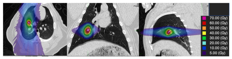
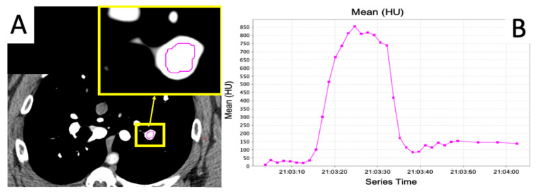
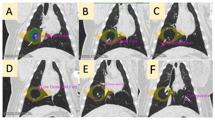
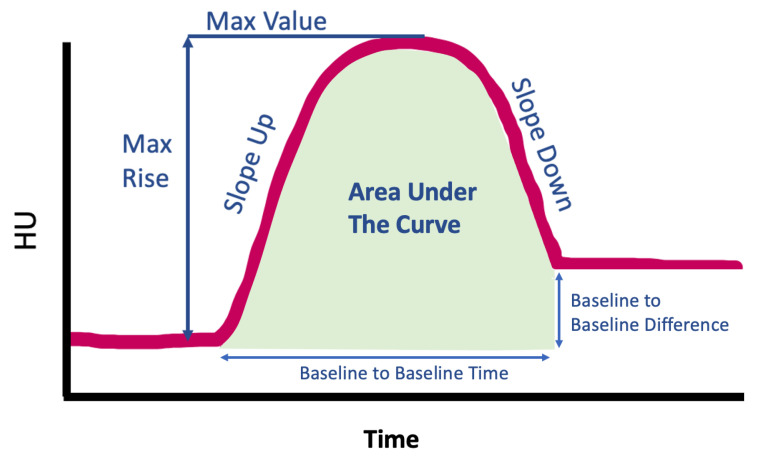
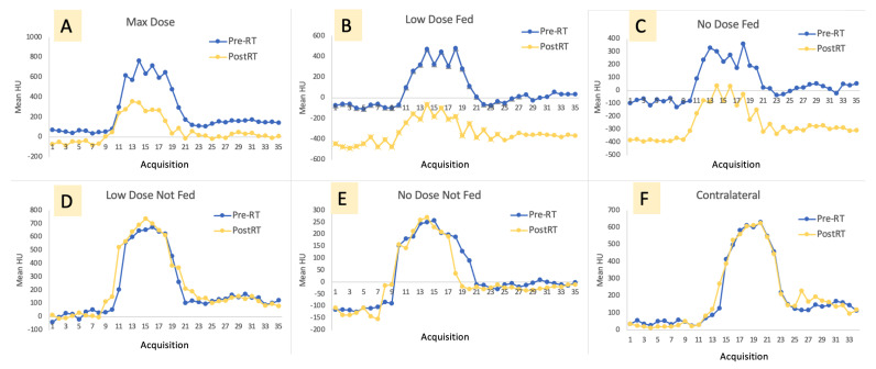
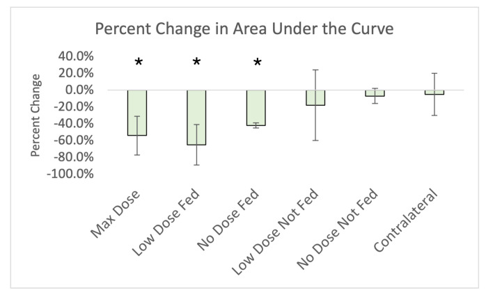
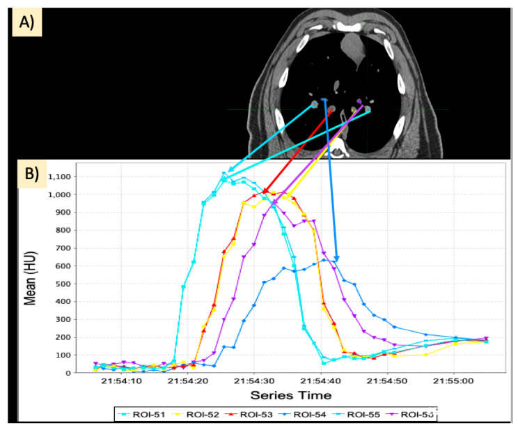
Recent functional lung imaging studies have presented evidence of an “indirect effect” on perfusion damage, where regions that are unirradiated or lowly irradiated but that are supplied by highly irradiated regions observe perfusion damage post-radiation therapy (RT). The purpose of this work was to investigate this effect using a contrast-enhanced dynamic CT protocol to measure perfusion change in five novel swine subjects. A cohort of five Wisconsin Miniature Swine (WMS) were given a research course of 60 Gy in five fractions delivered locally to a vessel in the lung using an Accuray Radixact tomotherapy system with Synchrony motion tracking to increase delivery accuracy. Imaging was performed prior to delivering RT and 3 months post-RT to yield a 28−36 frame image series showing contrast flowing in and out of the vasculature. Using MIM software, contours were placed in six vessels on each animal to yield a contrast flow curve for each vessel. The contours were placed as follows: one at the point of max dose, one low-irradiated (5−20 Gy) branching from the max dose vessel, one low-irradiated (5−20 Gy) not branching from the max dose vessel, one unirradiated (<5 Gy) branching from the max dose vessel, one unirradiated (<5 Gy) not branching from the max dose vessel, and one in the contralateral lung. Seven measurements (baseline-to-baseline time and difference, slope up and down, max rise and value, and area under the curve) were acquired for each vessel’s contrast flow curve in each subject. Paired Student t-tests showed statistically significant (p < 0.05) reductions in the area under the curve in the max dose, and both fed contours indicating an overall reduction in contrast in these regions. Additionally, there were statistically significant reductions observed when comparing pre- and post-RT in slope up and down in the max dose, low-dose fed, and no-dose fed contours but not the low-dose not-fed, no-dose not-fed, or contralateral contours. These findings suggest an indirect damage effect where irradiation of the vasculature causes a reduction in perfusion in irradiated regions as well as regions fed by the irradiated vasculature.

Keywords: functional avoidance; lung SBRT; perfusion; post-RT toxicity; swine model.


Conflict of interest statement

J.M.R. is a shareholder in VIDA Diagnostics, Inc.; G.E.C. receives licensing fees from VIDA Diagnostics, Inc.; and J.E.B. has ownership interest in MR Guidance, LLC.

Figures

Figure 1
Figure 1
Example dose distribution delivered to the Swine subjects.
Figure 2
Figure 2
Example of a curve showing the flow of contrast into and out of a vessel. (A) Example slice in a frame of the scan showing the placement of an ROI in a vessel. (B) Average Hounsfield Unit (HU) value inside the ROI over the frames of the scan. Increasing HU represents contrast flow into the vessel, and decreasing HU represents contrast flow out of the vessel.
Figure 3
Figure 3
Representative placement of contours analyzed. The point of max dose is shown in the center of the full dose distribution (A). The 5–20 Gy dose distribution is shown in (BD) to indicate the region of low dose. A point on the low-dose region fed by the max dose vessel (B) and not-fed (D) are placed. Points receiving no-dose fed by the max dose vessel and not-fed are placed in (C,E), respectively. Finally, a point in the contralateral lung is placed approximately where the max dose is mirrored on the ipsilateral lung (F).
Figure 4
Figure 4
Diagram showing the different measurements that were obtained in each contour.
Figure 5
Figure 5
Representative contrast curves pre- and post-RT in an example subject in the max dose contour (A), low-dose fed contour (B), no-dose fed contour (C), low-dose not-fed contour (D), no-dose not-fed contour (E), and contralateral lung (F). There is little change in the not-fed contours and contralateral lung contour, while the fed and max dose contours observe significant change.
Figure 6
Figure 6
Percent change in area under the curve for each contour analyzed. Each bar represents the average of the 5 subjects (or 4 in the case of the no-dose fed contour). Error bars are the standard deviation of the percent changes in subjects. Statistically significant results are denoted with a *.
Figure 7
Figure 7
Taken from Farr et al. [25]. SPECT/CT of a patient with tumor in the right lung before radiotherapy (A), planning CT with dose to the gross tumor volume in color wash, SPECT defined functional lung outlined in yellow (B), SPECT/CT 3-months post-RT (C). A dotted cyan oval is drawn to indicate a region that received low dose but did not experience perfusion decline. A magenta oval is drawn in another region that received low dose but did experience perfusion decline post-RT and is fed by an irradiated region. Reprinted with permission.
Figure 8
Figure 8
Taken from Thomas et al. [26]. Observed radiation dose–response on longitudinal perfusion SPECT/CT. (Upper row) Pre-treatment lung perfusion SPECT co-registered to planning CT and radiation isodose line rainbow overlay. (Lower row) Three-month post-treatment perfusion SPECT co-registered to planning CT and radiation isodose lines (rainbow overlay). SPECT window/level were normalized to out-of-field integral uptake. Regions within the treatment field show reductions in uptake that are correlated with radiation dose magnitude and spatial distribution. A dotted cyan oval is drawn to indicate a region that received low dose but did not experience perfusion decline. A magenta oval is drawn in another region that received low dose but did experience perfusion decline post-RT and is fed by an irradiated region. Reprinted with permission.
Figure 9
Figure 9
Dynamic contrast-CT data in different vasculature. (A) Different contours placed in different vasculature in the lung. (B) Corresponding contrast flow curves.

Similar articles

Cited by

References

    1. American Cancer Society . 2022-Cancer-Facts-and-Figures. American Cancer Society; Atlanta, GA, USA: 2022.
    1. Bradley J.D., Paulus R., Komaki R., Masters G., Blumenschein G., Schild S., Bogart J., Hu C., Forster K., Magliocco A., et al. Standard-dose versus high-dose conformal radiotherapy with concurrent and consolidation carboplatin plus paclitaxel with or without cetuximab for patients with stage IIIA or IIIB non-small-cell lung cancer (RTOG 0617): A randomised, two-by-two factorial phase 3 study. Lancet Oncol. 2015;16:187–199. doi: 10.1016/S1470-2045(14)71207-0. - DOI - PMC - PubMed
    1. Marks L., Yu X., Vujaskovic Z., Smalljr W., Folz R., Anscher M. Radiation-induced lung injury. Semin. Radiat. Oncol. 2003;13:333–345. doi: 10.1016/S1053-4296(03)00034-1. - DOI - PubMed
    1. Bates E.L., Bragg C.M., Wild J.M., Hatton M.Q., Ireland R.H. Functional image-based radiotherapy planning for non-small cell lung cancer: A simulation study. Radiother. Oncol. 2009;93:32–36. doi: 10.1016/j.radonc.2009.05.018. - DOI - PMC - PubMed
    1. Patton T.J., Bayouth J.E., Bednarz B.P., Fain S.B., Reinhardt J.M., Smilowitz J. Quantifying and Modeling Radiation Therapy-Induced Ventilation Changes and Investigating the Robustness of 4DCT-Based Functional Avoidance. The University of Wisconsin-Madison; Madison, WI, USA: 2018. Technical Report.

LinkOut - more resources