. 2022 Aug 20;22(16):6258.
doi: 10.3390/s22166258.

Infrared Target Detection Based on Joint Spatio-Temporal Filtering and L1 Norm Regularization

Affiliations

Infrared Target Detection Based on Joint Spatio-Temporal Filtering and L1 Norm Regularization

Enyong Xu et al. Sensors (Basel). .

Abstract

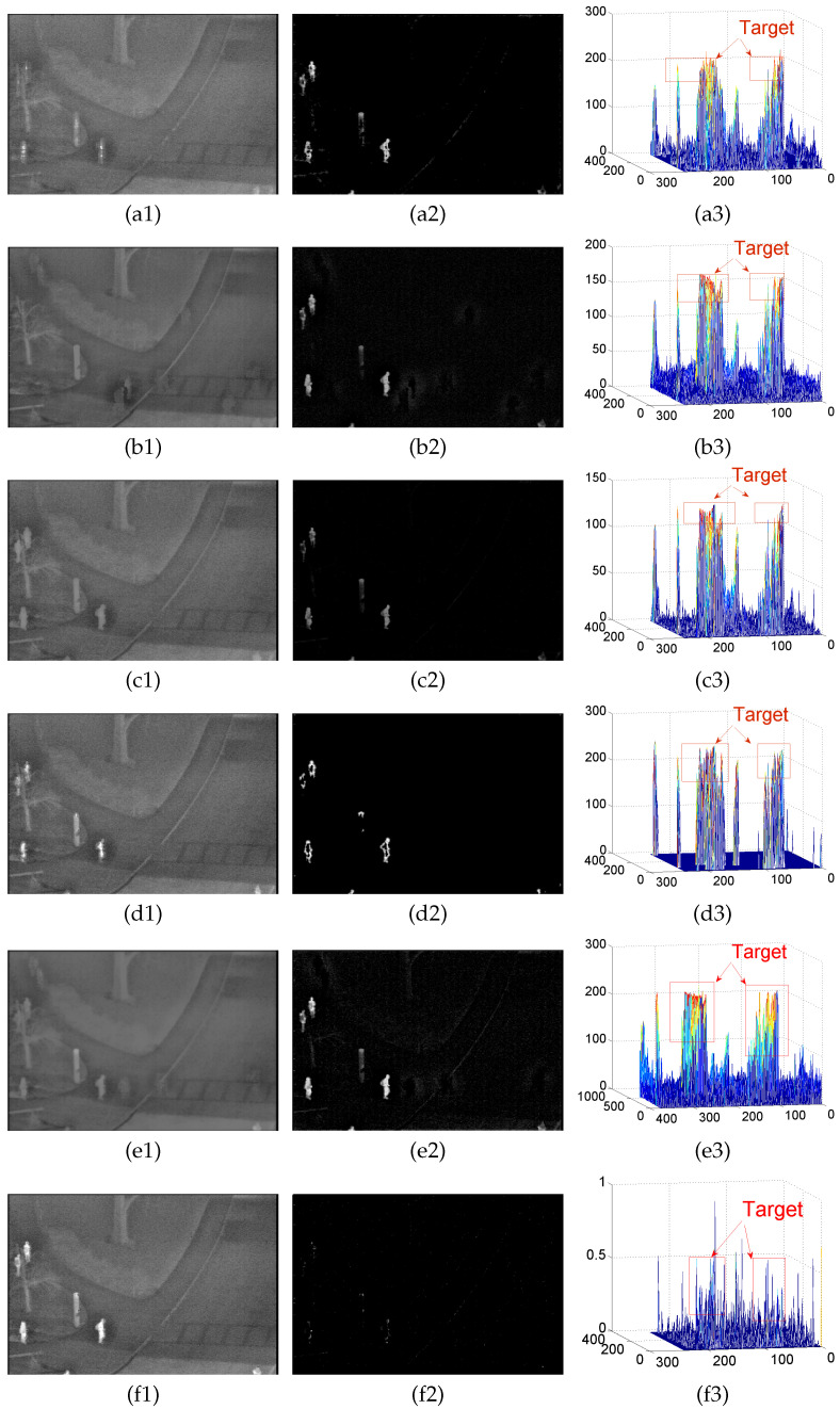
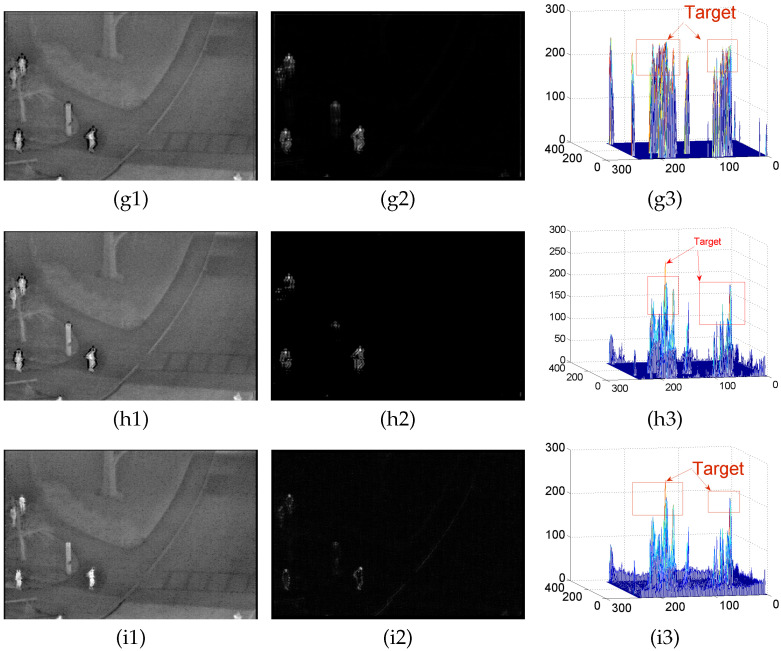
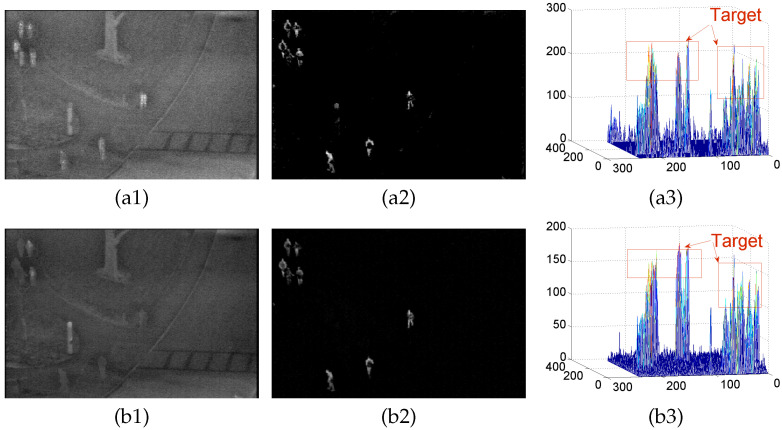
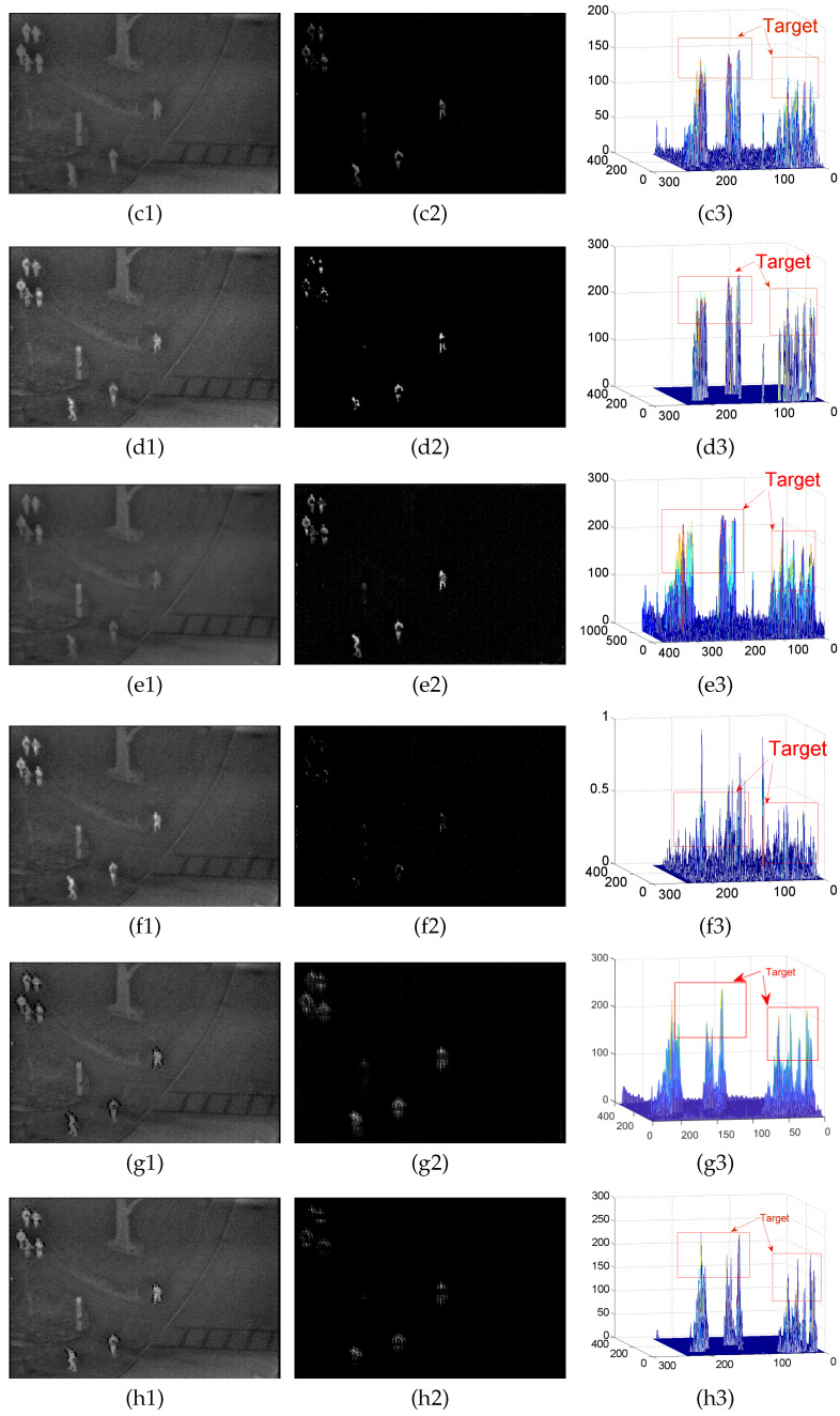
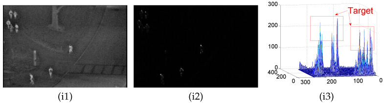
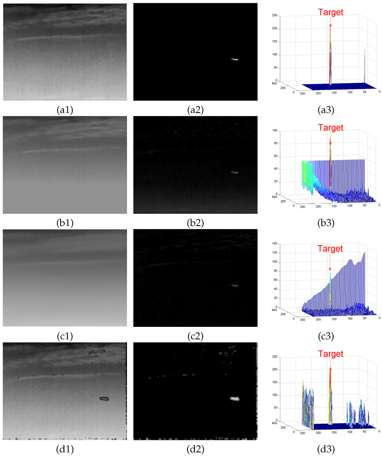
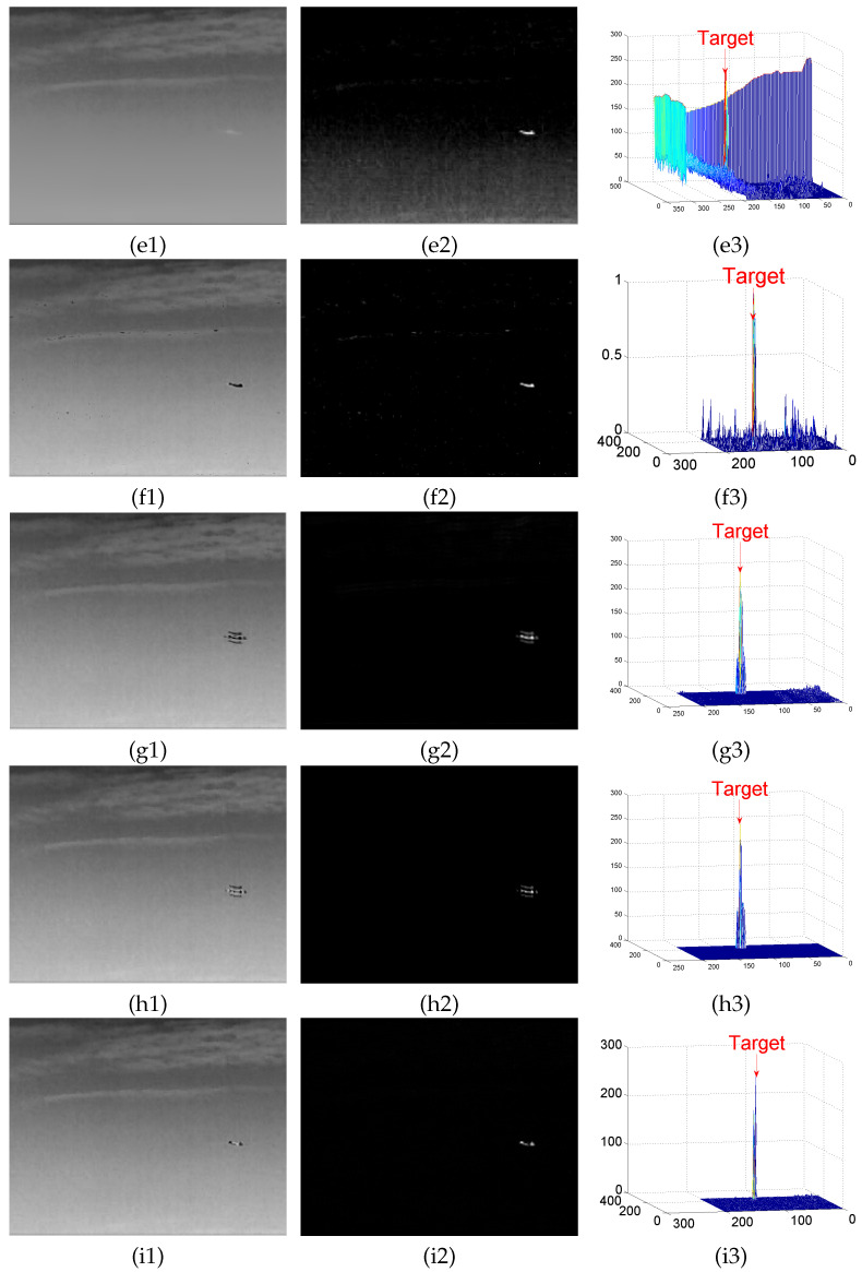
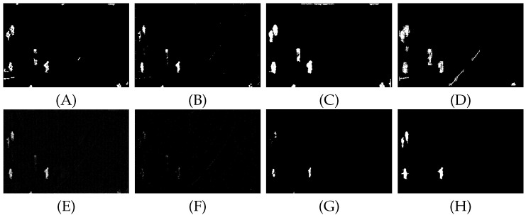
Infrared target detection is often disrupted by a complex background, resulting in a high false alarm and low target recognition. This paper proposes a robust principal component decomposition model with joint spatial and temporal filtering and L1 norm regularization to effectively suppress the complex backgrounds. The model establishes a new anisotropic Gaussian kernel diffusion function, which exploits the difference between the target and the background in the spatial domain to suppress the edge contours. Furthermore, in order to suppress the dynamically changing background, we construct an inversion model that combines temporal domain information and L1 norm regularization to globally constrain the low rank characteristics of the background, and characterize the target sparse component with L1 norm. Finally, the overlapping multiplier method is used for decomposition and reconstruction to complete the target detection.Through relevant experiments, the proposed background modeling method in this paper has a better background suppression effect in different scenes. The average values of the three evaluation indexes, SSIM, BSF and IC, are 0.986, 88.357 and 18.967, respectively. Meanwhile, the proposed detection method obtains a higher detection rate compared with other algorithms under the same false alarm rate.

Keywords: anisotropy; detection; infrared target; robust principal component decomposition model; spatio-temporal filtering.


Conflict of interest statement

The authors declare no conflict of interest.

Figures

Figure A1
Figure A1
(ai) denote the detection results of the PSTNN, RPCA, TV-PCP, VNTFR, ASTTV, SRWS, C2, C3, and proposed algorithm on sequence B, respectively, where (a1a3) denote the background map, the differential map, and the 3D map of the obtained differential map, respectively.
Figure A1
Figure A1
(ai) denote the detection results of the PSTNN, RPCA, TV-PCP, VNTFR, ASTTV, SRWS, C2, C3, and proposed algorithm on sequence B, respectively, where (a1a3) denote the background map, the differential map, and the 3D map of the obtained differential map, respectively.
Figure A2
Figure A2
(ai) denote the detection results of the PSTNN, RPCA, TV-PCP, VNTFR, ASTTV, SRWS, C2, C3, and proposed algorithm on sequence C, respectively, where (a1a3) denote the background map, the differential map, and the 3D map of the obtained differential map, respectively.
Figure A2
Figure A2
(ai) denote the detection results of the PSTNN, RPCA, TV-PCP, VNTFR, ASTTV, SRWS, C2, C3, and proposed algorithm on sequence C, respectively, where (a1a3) denote the background map, the differential map, and the 3D map of the obtained differential map, respectively.
Figure A2
Figure A2
(ai) denote the detection results of the PSTNN, RPCA, TV-PCP, VNTFR, ASTTV, SRWS, C2, C3, and proposed algorithm on sequence C, respectively, where (a1a3) denote the background map, the differential map, and the 3D map of the obtained differential map, respectively.
Figure A3
Figure A3
(ai) denote the detection results of the PSTNN, RPCA, TV-PCP, VNTFR, ASTTV, SRWS, C2, C3, and proposed algorithm on sequence D, respectively, where (a1a3) denote the background map, the differential map, and the 3D map of the obtained differential map, respectively.
Figure A3
Figure A3
(ai) denote the detection results of the PSTNN, RPCA, TV-PCP, VNTFR, ASTTV, SRWS, C2, C3, and proposed algorithm on sequence D, respectively, where (a1a3) denote the background map, the differential map, and the 3D map of the obtained differential map, respectively.
Figure A4
Figure A4
(ai) denote the detection results of the PSTNN, RPCA, TV-PCP, VNTFR, ASTTV, SRWS, C2, C3, and proposed algorithm on sequence E, respectively, where (a1a3) denote the background map, the differential map, and the 3D map of the obtained differential map, respectively.
Figure A4
Figure A4
(ai) denote the detection results of the PSTNN, RPCA, TV-PCP, VNTFR, ASTTV, SRWS, C2, C3, and proposed algorithm on sequence E, respectively, where (a1a3) denote the background map, the differential map, and the 3D map of the obtained differential map, respectively.
Figure A4
Figure A4
(ai) denote the detection results of the PSTNN, RPCA, TV-PCP, VNTFR, ASTTV, SRWS, C2, C3, and proposed algorithm on sequence E, respectively, where (a1a3) denote the background map, the differential map, and the 3D map of the obtained differential map, respectively.
Figure A5
Figure A5
(ai) denote the detection results of the PSTNN, RPCA, TV-PCP, VNTFR, ASTTV, SRWS, C2, C3, and proposed algorithm on sequence F, respectively, where (a1a3) denote the background map, the differential map, and the 3D map of the obtained differential map, respectively.
Figure A5
Figure A5
(ai) denote the detection results of the PSTNN, RPCA, TV-PCP, VNTFR, ASTTV, SRWS, C2, C3, and proposed algorithm on sequence F, respectively, where (a1a3) denote the background map, the differential map, and the 3D map of the obtained differential map, respectively.
Figure A5
Figure A5
(ai) denote the detection results of the PSTNN, RPCA, TV-PCP, VNTFR, ASTTV, SRWS, C2, C3, and proposed algorithm on sequence F, respectively, where (a1a3) denote the background map, the differential map, and the 3D map of the obtained differential map, respectively.
Figure A6
Figure A6
(ai) denote the detection results of the PSTNN, RPCA, TV-PCP, VNTFR, ASTTV, SRWS, C2, C3, and proposed algorithm on sequence G, respectively, where (a1a3) denote the background map, the differential map, and the 3D map of the obtained differential map, respectively.
Figure A6
Figure A6
(ai) denote the detection results of the PSTNN, RPCA, TV-PCP, VNTFR, ASTTV, SRWS, C2, C3, and proposed algorithm on sequence G, respectively, where (a1a3) denote the background map, the differential map, and the 3D map of the obtained differential map, respectively.
Figure A7
Figure A7
(ai) denote the detection results of the PSTNN, RPCA, TV-PCP, VNTFR, ASTTV, SRWS, C2, C3, and proposed algorithm on sequence H, respectively, where (a1a3) denote the background map, the differential map, and the 3D map of the obtained differential map, respectively.
Figure A7
Figure A7
(ai) denote the detection results of the PSTNN, RPCA, TV-PCP, VNTFR, ASTTV, SRWS, C2, C3, and proposed algorithm on sequence H, respectively, where (a1a3) denote the background map, the differential map, and the 3D map of the obtained differential map, respectively.
Figure A8
Figure A8
(AH) shows the detection results of eight algorithms PSTNN, TV-PCP, VNTFR, anisotropy, ASTTV, SRWS, RPCA and propose method, respectively, under sequence B.
Figure A9
Figure A9
(AH) shows the detection results of eight algorithms PSTNN, TV-PCP, VNTFR, anisotropy, ASTTV, SRWS, RPCA and propose method, respectively, under sequence C.
Figure A10
Figure A10
(AH) shows the detection results of eight algorithms PSTNN, TV-PCP, VNTFR, anisotropy, ASTTV, SRWS, RPCA and propose method, respectively, under sequence D.
Figure A11
Figure A11
(AH) shows the detection results of eight algorithms PSTNN, TV-PCP, VNTFR, anisotropy, ASTTV, SRWS, RPCA and propose method, respectively, under sequence E.
Figure A12
Figure A12
(AH) shows the detection results of eight algorithms PSTNN, TV-PCP, VNTFR, anisotropy, ASTTV, SRWS, RPCA and propose method, respectively, under sequence F.
Figure A13
Figure A13
(AH) shows the detection results of eight algorithms PSTNN, TV-PCP, VNTFR, anisotropy, ASTTV, SRWS, RPCA and propose method, respectively, under sequence G.
Figure A14
Figure A14
(AH) shows the detection results of eight algorithms PSTNN, TV-PCP, VNTFR, anisotropy, ASTTV, SRWS, RPCA and propose method, respectively, under sequence H.
Figure 1
Figure 1
Gradient perception curve of kernel function.
Figure 2
Figure 2
Comparison of gradient perception of kernel diffusion function. All functions were plotted for k=0.1.
Figure 3
Figure 3
The flow chart of the proposed method.
Figure 4
Figure 4
(AH) are representative images of eight sequences.
Figure 5
Figure 5
(ai) denote the detection results of the PSTNN, RPCA, TV-PCP, VNTFR, ASTTV, SRWS, C2, C3, and the proposed algorithm on sequence A, respectively, where (a1a3) denote the background map, the differential map, and the 3D map of the obtained differential map, respectively.
Figure 6
Figure 6
(AH) show the detection results of eight algorithms PSTNN, TV-PCP, VNTFR, anisotropy, ASTTV, SRWS, RPCA and propose methods, respectively, under sequence A.
Figure 7
Figure 7
(ah) show the ROC curves of eight sequences, respectively.

References

    1. Fan X., Guo H., Xu Z., Li B. Dim and Small Targets Detection in Sequence Images Based on spatio-temporal Motion Characteristics. Math. Probl. Eng. 2020;2020:7164859.
    1. Li Q., Nie J., Qu S. A small target detection algorithm in infrared image by combining multi-response fusion and local contrast enhancement. Opt.-Int. J. Light Electron. Opt. 2021;241:166919. doi: 10.1016/j.ijleo.2021.166919. - DOI
    1. Deng H., Sun X., Liu M., Ye C. Infrared small-target detection using multiscale gray difference weighted image entropy. IEEE Trans. Aerosp. Electron. Syst. 2016;52:60–72. doi: 10.1109/TAES.2015.140878. - DOI
    1. Xiong B., Huang X., Wang M. Local Gradient Field Feature Contrast Measure for Infrared Small Target Detection. IEEE Geosci. Remote. Sens. Lett. 2020;18:553–557. doi: 10.1109/LGRS.2020.2976208. - DOI
    1. Fan X., Xu Z., Zhang J., Huang Y., Peng Z., Wei Z., Guo H. Dim small target detection based on high-order cumulant of motion estimation. Infrared Phys. Technol. 2019;99:86–101. doi: 10.1016/j.infrared.2019.04.008. - DOI

LinkOut - more resources