. 2022 Aug 26;8(34):eabq2345.
doi: 10.1126/sciadv.abq2345. Epub 2022 Aug 26.

Soft-robotic ciliated epidermis for reconfigurable coordinated fluid manipulation

Affiliations

Soft-robotic ciliated epidermis for reconfigurable coordinated fluid manipulation

Ziyu Ren et al. Sci Adv. .

Abstract

The fluid manipulation capabilities of current artificial cilia are severely handicapped by the inability to reconfigure near-surface flow on various static or dynamically deforming three-dimensional (3D) substrates. To overcome this challenge, we propose an electrically driven soft-robotic ciliated epidermis with multiple independently controlled polypyrrole bending actuators. The beating kinematics and the coordination of multiple actuators can be dynamically reconfigured to control the strength and direction of fluid transportation. We achieve fluid transportation along and perpendicular to the beating directions of the actuator arrays, and toward or away from the substrate. The ciliated epidermises are bendable and stretchable and can be deployed on various static or dynamically deforming 3D surfaces. They enable previously difficult to obtain fluid manipulation functionalities, such as transporting fluid in tubular structures or enhancing fluid transportation near dynamically bending and expanding surfaces.


Figures

Fig. 1.
Fig. 1.. Design and fabrication of the soft-robotic ciliated epidermis.
(A) Design of the ciliated actuator array. In the design shown here, all the actuators on the same array are actuated simultaneously. However, the actuators on the same array can also be independently controlled if the electrodes are separated. (B) Cross-sectional scanning electron microscopy image of the PPy actuator. The PPy layer is around 1.3 μm thick, the Au/Cr layer is around 230 nm thick, and the parylene C layer is around 0.8 μm thick. (C) Photo of a ciliated epidermis patched on a curved surface. (D) Schematic of a typical fabrication process of the ciliated epidermis.
Fig. 2.
Fig. 2.. Characterization of PPy actuators.
(A) The actuators slightly bend toward the side of the parylene C layer after being released from the wafer. When putting the actuators in the electrolyte, the actuators curl toward the side of the parylene C layer with a very large curvature. After actuating the actuators in the electrolyte for several cycles with a square wave (−0.85 to 0.1 V; duty cycle, 50%), the actuators gradually expand. The actuators return to the initial state at 0 V and achieve the maximum curvature at −0.85 V. (B) Cyclic voltammograms at different measurement conditions (i to iii) and the capacitance calculated from the C-V curve (iv). (C) Influence of different factors on the bending amplitude. (i) Influence of gold layer thickness. (ii) Influence of parylene C layer thickness. (iii) Influence of PPy layer thickness. (iv) Influence of Na+ concentration. In (i) to (iii), the values are averaged from the measurements of three samples.
Fig. 3.
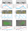
Fig. 3.. Performance characterization of a ciliated actuator array.
(A) Actuator kinematics quantified by curvature variation. Two control signals are prescribed to produce different oxidation and reduction durations. (B) Flow structures induced by the two beating modes. By tuning the duration of the oxidation and reduction phases, the fluids are transported in different directions. The flow velocities are averaged along the red dashed line. (C) Transportation performances of the two beating modes. Massless virtual particles are tracked on the basis of the flow fields obtained by particle image velocimetry measurements. The center of mass (COM) displacements parallel and normal to the substrate are plotted. The red dots indicate the final positions of the virtual particles after three beating cycles. The green lines connect the initial and final positions of the particles. In (B) and (C), the planting angle γ of the actuator is 45°. The actuators shown here are 1.5 mm in length.
Fig. 4.
Fig. 4.. Reconfiguration of the beating mode and the phase shift between the actuator arrays for enabling different fluid manipulation performances.
(A) Producing a phase shift between the actuator arrays on a flat surface. (i to ii) By tuning the directions of the metachronal waves and the beating modes of the actuators, the fluid can be transported parallel to the substrate in two directions. (iii to iv) By producing metachronal waves with different transmitting directions, the fluid can be pushed away or drawn toward the substrate. (v) By changing the phase shift (φx) between the actuator arrays and the beating frequency of the actuators, the flow strength parallel to the substrate can be tuned, which is quantified by ∣Qx∣. Qx is calculated along the red dashed line in (i). The values are averaged from ∣Qx∣ of five consecutive beating cycles. (B) Producing phase shift between the actuator arrays on a sinusoidal substrate. (i to ii) By tuning the directions of the metachronal waves and the beating modes, the ciliated epidermis can transport fluids along the substrate in two directions. (iii to v) By tuning the reversal point of the two metachronal waves departing from each other, the locations where the fluids are pushed away from the substrate can be shifted. (vi) By reversing the directions of the metachronal waves in (v), the fluids can be drawn toward the substrate at the same location. In (A) and (B), the side views of the ciliated epidermis are depicted below the flow fields. The black arrows indicate the directions of the metachronal waves.
Fig. 5.
Fig. 5.. Reconfiguration of the beating mode and the phase shift along the array direction for enabling different fluid manipulation performances.
(A) Producing phase shift between the actuator arrays on a flat substrate. (i to iv) Flow fields produced by the ciliated epidermis with out-of-phase motion along the array (φy ≠ 0). The phase shift between the arrays (φx) is kept to be 2π/7. (B) Quantification of the flow field. (i) Average flow velocities in the x direction (U¯x) along cut lines 1 and 2. U¯x achieved at φy = 2π/7 is larger than at φy = 0. (ii) Q calculated across cut line 2 at different φy. The values are averaged from ∣Qx∣ of five consecutive beating cycles. (iii) U¯x and U¯y along cut line 3. The fluid transportation along the x direction is suppressed, while the transportation along the y direction is amplified. (iv) U¯x along cut lines 4 and 5. Two fluid transportation regions with different transportation directions are achieved.
Fig. 6.
Fig. 6.. Deployment of the ciliated epidermis on different curved and dynamically deforming surfaces.
(A) Deployment of the ciliated epidermis inside a cylindrical tube. The ciliated epidermis is wrapped and patched to the inner surface of the tube. When the actuators are turned on, the dyes injected into the tube are pumped out. (B) Independently controlling each actuator of a 10 × 10 actuator matrix on a flat surface. The actuator matrix can dynamically display different letters at different locations. The actuators being activated are shaded with a red color. (C) Deployment of the ciliated epidermis on a dynamically stretchable 3D surface. The ciliated epidermis is patched to the outer surface of a pneumatically driven soft actuator. The epidermis can still transport fluids near the substrate when the surface is stretched due to inflation. (D) Enhancing the downstream flow produced by a flapping membrane fixed at one end. The ciliated epidermis is patched to one side of the deforming membrane. When the ciliated epidermis is turned on, the flapping substrate produces a stronger flow downstream. (E) Changing the wake flow shedding pattern of a flapping membrane translating upward with a constant speed. The ciliated epidermis is patched on top of a flapping membrane. When the ciliated epidermis is turned on, more dyes are shed from the top layer of the membrane. The red double arrows indicate the change in dye trace area.

References

    1. Gilpin W., Prakash V. N., Prakash M., Vortex arrays and ciliary tangles underlie the feeding-swimming trade-off in starfish larvae. Nat. Phys. 13, 380–386 (2017).
    1. Wan K. Y., Hurlimann S. K., Fenix A. M., McGillivary R. M., Makushok T., Burns E., Sheung J. Y., Marshall W. F., Reorganization of complex ciliary flows around regenerating Stentor coeruleus. Philos. Trans. R. Soc. B Biol. Sci. 375, 20190167 (2020). - PMC - PubMed
    1. Shapiro O. H., Fernandez V. I., Garren M., Guasto J. S., Debaillon-Vesque F. P., Kramarsky-Winter E., Vardi A., Stocker R., Vortical ciliary flows actively enhance mass transport in reef corals. Proc. Natl. Acad. Sci. U.S.A. 111, 13391–13396 (2014). - PMC - PubMed
    1. Tamm S. L., Cilia and the life of ctenophores. Invertebr. Biol. 133, 1–46 (2014).
    1. Gemmell B. J., Colin S. P., Costello J. H., Sutherland K. R., A ctenophore (comb jelly) employs vortex rebound dynamics and outperforms other gelatinous swimmers. R. Soc. Open Sci. 6, 181615 (2019). - PMC - PubMed