Review
. 2022 Oct;9(29):e2203291.
doi: 10.1002/advs.202203291. Epub 2022 Aug 28.

Biofilms: Formation, Research Models, Potential Targets, and Methods for Prevention and Treatment

Affiliations
Review

Biofilms: Formation, Research Models, Potential Targets, and Methods for Prevention and Treatment

Yajuan Su et al. Adv Sci (Weinh). 2022 Oct.

Abstract

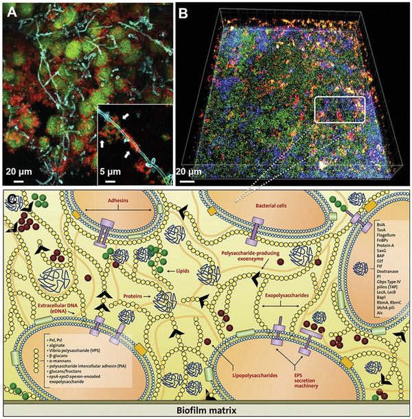
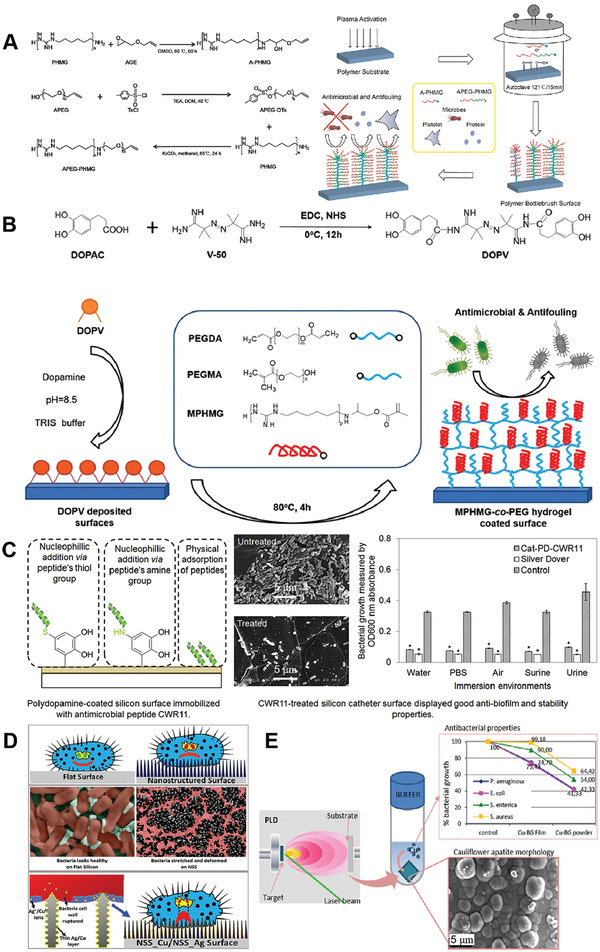
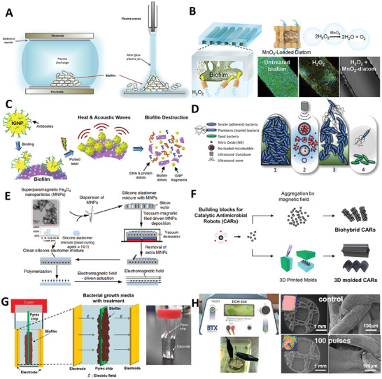
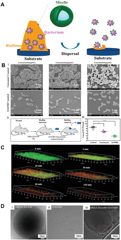
Due to the continuous rise in biofilm-related infections, biofilms seriously threaten human health. The formation of biofilms makes conventional antibiotics ineffective and dampens immune clearance. Therefore, it is important to understand the mechanisms of biofilm formation and develop novel strategies to treat biofilms more effectively. This review article begins with an introduction to biofilm formation in various clinical scenarios and their corresponding therapy. Established biofilm models used in research are then summarized. The potential targets which may assist in the development of new strategies for combating biofilms are further discussed. The novel technologies developed recently for the prevention and treatment of biofilms including antimicrobial surface coatings, physical removal of biofilms, development of new antimicrobial molecules, and delivery of antimicrobial agents are subsequently presented. Finally, directions for future studies are pointed out.

Keywords: biofilms; formation; management; models; targets.


Conflict of interest statement

The authors declare no conflict of interest.

Figures

Figure 1
Figure 1
Representative bacterial biofilms within the clinical setting. A) The process of DFU wound infection, chronicization, and biofilm colonization. Reproduced with permission.[ 28 ] Copyright 2019, MDPI. B) Representative images of biofilms on the full‐thickness burn wounds. I): Large collections of gram‐positive cocci form a biofilm on the surface of an ulcerated burn wound. Wound dressing remnants are present on the top left. II): Low power transmission electron micrograph of a mixed bacterial biofilm consisting of rods and cocci, some of which are degenerated (arrows). III): Scanning electron micrograph of the edge of an escharotomy site. The burn surface can be observed on the top right. A large collection of mixed bacteria with the typical appearance of a biofilm can be seen below the surface within dermal collagen. Reproduced with permission.[ 45 ] Copyright 2010, Elsevier. C) In vivo evidence suggesting H. pylori biofilm formation in the gastric glands of humans. I): Large aggregates of H. pylori colonizing the surface of gastric glands; II): H. pylori aggregates colonizing the neck of gastric glands, with proliferative cells; III) colonies of H. pylori deep in the gland, in the vicinity of stem cells. H. pylori stained in green, actin stained in red and DNA nucleus stained in blue. Reproduced with permission.[ 58 ] Copyright 2019, Frontiers Media S.A. D) Dental plaque architecture: The EPS matrix, spatial organization, and polymicrobial composition. I): Plaque biofilm from a caries‐active subject: microscopic image (inset) of plaque‐biofilm showing a selected area containing bacterial cells (highlighted in orange) enmeshed in EPS (in dark blue); the image was pseudo‐colored using Adobe Photoshop software for visualization purposes. II): Bacterial clusters (green) surrounded by EPS matrix (red) detected in mature mixed‐species oral biofilms formed in sucrose. III): Spatial organization of human dental plaque showing multiple clusters of varying sizes containing different microbial species. Reproduced with permission.[ 71 ] Copyright 2018, Elsevier. E) I): A catheter was removed surgically that had been indwelling suprapubically for 6 months. Crystalline material completely covered the eyehole and balloon of the hydrogel‐coated latex catheter. II): A cross‐section of a silicone catheter that had been indwelling for 8 weeks. The image shows that the central lumen was occluded by crystalline biofilm. III): A longitudinal section of a silver‐hydrogel‐coated latex catheter that became blocked after 11 days in situ. Reproduced with permission.[ 86 ] Copyright 2008, Springer Nature.
Figure 2
Figure 2
A representative in vitro biofilm model. A) Photograph showing a methacrylate stent with 10 mm wide and 7 mm high and an internal drilling with a diameter of 2.7 and 5 mm deep to support the implants in a fixed position allowing the exposure of the coronal third of the implant surface. B) CLSM Images obtained at 12 (I), 24 (II), 48 (III), 72 (IV), 96 (V), and 120 (VI) h of incubation of biofilms over whole dental implants which were stained using LIVE/DEAD BacLight Kit with live bacteria in green, dead bacteria in red, and implant surface in blue. C) SEM images showed biofilm growth from 48 to 120 h over whole dental implants. I): Biofilms after 48 h of incubation, with a complex morphology, in which Fusobacterium nucleatum formed networks with the adhered microcolonies of bacteria. II,III): Biofilms after 72 and 96 h of incubation, indicating the bacteria were in the expected larger stacks (growing masses of bacterial cells) and presence of broad channels (green arrow) and the cell mass and ECM surrounding bacteria in the biofilm (white arrows). IV): The biofilms after incubation from 72 to 120 h did not change in architecture. Reproduced with permission.[ 129 , 130 ] Copyright 2019, Wiley‐VCH.
Figure 3
Figure 3
Two representative ex vivo biofilm models. A) An ex vivo lung model to study bronchioles infected with P. aeruginosa biofilms. I): EVPL in situ in ASM at 19 h post‐inoculation. Uninfected bronchiolar tissue retained its normal appearance: a pinkish‐white square with no noticeable degradation, surrounded by clear ASM. The laboratory strain PA14 did not show visible growth either on the tissue or in the surrounding ASM at this early stage; PAO1, in contrast, had grown extensively in the liquid ASM surrounding the tissue (green‐yellow pigmentation due to production of pyoverdine) but did not yet show any noticeable growth on the tissue itself‐note pinkish‐white square of tissue sitting in the liquid bacterial culture. In contrast, CF isolates of P. aeruginosa (e.g., SED‐41 and SED‐43) showed growth as frond‐like aggregates on and connected to the cubes of tissue, very different from the dense planktonic growth of PAO1. II) By 4 days post‐inoculation, CF isolates of P. aeruginosa had grown to a high density on EVPL. The image shows three replica infections of SED‐41 (top row) and SED‐43 (bottom row) after washing the tissue with phosphate‐buffered saline to remove non‐adhering cells: a coating of sticky P. aeruginosa, with blue‐green pigmentation (pyoverdine and pyocyanin), was left behind. III) These biofilms were noticeably mucoid (e.g., SED‐41). Reproduced with permission.[ 135 ] Copyright 2016, Microbiology Society. B) S. aureus forms macroscopic biofilm aggregates in the synovial fluid of several different species. Equine, human or porcine synovial fluid was infected at 1×10⁶ CFU/mL with S. aureus (ATCC25923) and incubated overnight at 37 °C in a microaerophilic chamber on a shaker at 120 rpm to mimic the joint environment. I): Macroscopic biofilm aggregates were observed in synovial fluid in all three species and photographed. II): Aggregates were removed from the synovial fluid, fixed, dehydrated in ethanol, sputter coated, and imaged with an SEM, showing bacteria nested within a polymeric cord‐like ECM. III) Aggregates were stained with WGA in blue for carbohydrates, SYTO9 in green for nucleic acids, and SYPRO in red for proteinaceous content. 3D CLSM images were reconstructed by sequential Z‐stacking and tile scanning with Velocity software. Reproduced with permission.[ 136 ] Copyright 2019, PLOS.
Figure 4
Figure 4
Two representative in vivo biofilm models. A) Photographs showing right knees of C57BL/6 mice after surgical implantation for 6 weeks. I): In the control animal, anatomical structures were preserved, with clear visualization of the patella and patellar tendon. II): In the animal infected with S. aureus, the patella was difficult to identify on superficial dissection. The underlying joint capsule (arrow) was distended because of being full of purulent, foul‐smelling, yellow material. III): Upon entering the joint, the proximal aspect of the tibia was fragmented and friable. The implant (arrowhead) was found within soft bone, was grossly loose, and was covered with yellow intra‐articular material (arrow). Reproduced with permission.[ 143 ] Copyright 2017, The Journal of Bone and Joint Surgery, Inc. B) Fluorescence in situ hybridization (FISH) of in vitro grown S. aureus LS1 biofilms on a polytetrafluoroethylene catheter. The section was hybridized with the pan‐bacterial probe EUB338FITC (green), S. aureus specific probe SAUCy3 (yellow), nonsense probe NON338 (magenta), and nucleic acid was stained with DAPI (blue). I): Overview of the biofilm located on the outside of the catheter, showing multilayered cocci with strong fluorescence signals. II): High magnification image of boxed area in (I) showing merged image of all channels, indicating multilayered cocci with strong FISH signals. III–V): Black and white images of the single fluorescence channels showing nucleic acid staining with DAPI (III), pan‐bacterial probe EUB338FITC (IV), and S. aureus specific SAUCy3 signals (V). Note that all bacteria stained with EUB338 also show signals with probe SAUCy3. Reproduced with permission.[ 144 ] Copyright 2017, Elsevier.
Figure 5
Figure 5
Compositions and functions of biofilm matrix in structured microbial communities. A) confocal fluorescence images of developed cross‐kingdom dental biofilms within ECM (red); inset shows Streptococcus mutans (green)‐Candida albicans (cyan) interactions mediated by ECM (white arrows). B) 3D reconstruction of CLSM images of in vitro oral biofilms after matrix staining. C) A schematic representation of the main components of the biofilm matrix and their functions. The biofilm matrix consisting of a wide array of functional biomolecules serves as a scaffold for structural support and a dynamic milieu that provides varying chemical and physical signals to microbial communities, promoting a biofilm lifestyle. Reproduced with permission.[ 145 ] Copyright 2020, Elsevier.
Figure 6
Figure 6
Typical examples of antimicrobial surface coatings. A) Polymer brushes‐based coatings. Reproduced with permission.[ 193 ] Copyright 2017, Wiley‐VCH. B) Anti‐adhesive hydrogels. Reproduced with permission.[ 194 ] Copyright 2019, Wiley‐VCH. C) AMP conjugates. Reproduced with permission.[ 197 ] Copyright 2015, Elsevier. D) Nanopillar array coatings. Reproduced with permission.[ 204 ] Copyright 2017, American Chemical Society. E) Nanocomposite coatings. Reproduced with permission.[ 206 ] Copyright 2019, American Chemical Society.
Figure 7
Figure 7
Typical methods of the physical removal of biofilms. A) Non‐thermo plasma. Reproduced with permission.[ 213 ] Copyright 2018, Elsevier. B) Microbubbles. Reproduced with permission.[ 227 ] Copyright 2018, American Chemical Society. C) Photothermal therapy. Reproduced with permission.[ 236 ] Copyright 2019, Elsevier. D) Ultrasound transducer. Reproduced with permission.[ 241 ] Copyright 2019, John Wiley & Sons Ltd and Society for Applied Microbiology. E) Magnetically driven active topography. Reproduced with permission.[ 247 ] Copyright 2020, Springer Nature. F) Catalytic antimicrobial robots. Reproduced with permission.[ 257 ] Copyright 2019, American Association of the Advancement of Science. G) Electrical stimulation. Reproduced with permission.[ 260 ] Copyright 2015, Springer Nature. H) Pulsed electric fields. Reproduced with permission.[ 263 ] Copyright 2016, Wiley‐VCH.
Figure 8
Figure 8
Block copolymer nanoparticles remove biofilms via nanoscale bacterial debridement. A) The possible mechanism of preformed biofilm removal by DA95B5 NPs. B) I): Representative SEM images of Gram‐positive bacteria. MRSA BAA40, VRE, and OG1RF biofilms on pegs of the MBEC biofilm inoculator before and after DA95B5 treatment (with 128 µg mL−1). II): Schematic illustrating DA95B5/vancomycin‐soaked hydrogels against MRSA BAA40 biofilms in an established murine excision wound model. III): Log CFU per wound from hydrogels alone and DA95B5‐soaked (2.5 mg kg−1) and vancomycin‐soaked (2.5 mg kg−1) hydrogels. Each type of hydrogel was applied 3 times at 4 h intervals before plating for CFU determination on agar plates. C) Penetration profiles of polymers at different time points. Time‐lapse 3D confocal images of MRSA BAA40 biofilms treated by DA95B5 at 128 µg mL−1 with incubation times of 0, 5, 10, 30, 60, and 120 min, showing the dispersal of biofilms (Green is live bacterial cells, Red is dead bacterial cells). D) Effect of DA95B5 on the properties of three Gram‐positive strains. Cryo‐TEM images showing I) MRSA BAA40 bacteria, II) DA95B5 NPs in PBS buffer, and III) the location of DA95B5 NPs in the MRSA BAA40 bacteria. The arrows denote NPs coated onto the bacterial surface. Reproduced with permission.[ 317 ] Copyright 2018, American Chemical Society.
Figure 9
Figure 9
Liposomes containing cinnamon oil against MRSA biofilms. A) Schematic illustrating liposomes containing cinnamon oil with anti‐biofilm activity against MRSA biofilms. B) SEM of MRSA biofilms before and after the treatment of liposomes containing cinnamon oil. C) CLSM images of MRSA biofilms before and after the treatment of liposomes containing cinnamon oil. Reproduced with permission.[ 331 ] Copyright 2016, Taylor & Francis Group.
Figure 10
Figure 10
Two distinct amphipathic peptide antibiotics with antibiofilm efficacy. A) N‐labeled leucine in horine (K) and verine‐L (L) indicates an H‐N vector (red) parallel to membrane surface, which allows to position the 3D structure of horine (left) and verine‐L (right) on the lipid bilayer so that the H‐N vector (in ball‐and‐stick) is approximately parallel to the bacterial membranes. B) SEM of S. aureus and K. pneumoniae before and after the AMP treatment. C) in vitro antibiofilm efficacy of horine (green) and verine (gold). I): Horine and verine (2 × MIC) killed the exponential phase S. aureus USA300 LAC in 120 min. II): The two peptides (2 × MIC) also killed nafcillin‐induced persisters of S. aureus. III): Verine, but not doripenem, inhibited the attachment of K. pneumoniae E406‐17 in a dose‐dependent manner. IV): Horine disrupted the S. aureus biofilms established in 48 h. In the confocal images, live bacteria in the untreated control are in V) green and VI) dead bacteria treated by 16 µm of horine are in red. VII): Verine was effective in disrupting the Klebsiella biofilms established in 48 h. In the confocal images, live K. pneumoniae are in green, and dead K. pneumoniae are in IX) red. Reproduced with permission.[ 347 ] Copyright 2020, National Academy of Science.
Figure 11
Figure 11
Microneedle‐based dressings for eradication of biofilms on skin wounds. A) Schematic illustrating Janus‐type antimicrobial dressings consisting of molecularly engineered peptide‐loaded electrospun nanofiber membranes and microneedle arrays for the treatment of biofilms in chronic wounds. B) Photograph showing the biofilm treatment by Janus‐type antimicrobial dressings in an ex vivo biofilm‐containing human skin wound model. C) The antibiofilm efficacy test of Janus‐type dressings in an ex vivo human skin wound model. The dressings were changed three times every 24 h. D) Live/dead staining for the tissue collected from wounds after 24 h of MRSA inoculation and subsequent 24 h of 2% mupirocin treatment, indicating the biofilm formation in type II diabetic mice wounds. E) Antibiofilm efficacy of Janus‐type antimicrobial dressings in vivo. The dressings were changed three times every 24 h. F) Antibiofilm efficacy of Janus‐type dressings against P. aeruginosa/MRSA blend biofilms in an ex vivo human skin wound model. The dressings were changed three times every 24 h. PCL‐F127: PCL‐F127 nanofibers. PCLF127/W379: W379 peptide‐loaded PCL‐F127 nanofibers. PCL‐F127/W379+aqueous W379: W379 peptide‐loaded PCL‐F127 nanofibers + free W379 peptides. PCL‐F127/W379+PVP/W379 MN: Janus‐type dressing composed of W379 peptide‐loaded PCL‐F127 nanofiber membrane and W379 peptide‐loaded microneedle arrays. Without treatment: no treatment for the wounds. Reproduced with permission.[ 353 ] Copyright 2020, American Chemical Society.

References

    1. Dufour D., Leung V., Lévesque C. M., Endod. Topics 2010, 22, 2.
    1. Costerton J. W., Stewart P. S., Greenberg E. P., Science 1999, 284, 1318. - PubMed
    1. Flemming H.‐C., Wingender J., Nat. Rev. Microbiol. 2010, 8, 623. - PubMed
    1. Blackledge M. S., Worthington R. J., Melander C., Curr. Opin. Pharmacol. 2013, 13, 699. - PMC - PubMed
    1. Kleinman H. K., Philp D., Hoffman M. P., Curr. Opin. Pharmacol. 2003, 14, 526. - PubMed

Publication types

Substances

LinkOut - more resources