. 2022 Aug 29;6(1):37.
doi: 10.1186/s41747-022-00292-y.

Computation of contrast-enhanced perfusion using only two CT scan phases: a proof-of-concept study on abdominal organs

Affiliations

Computation of contrast-enhanced perfusion using only two CT scan phases: a proof-of-concept study on abdominal organs

Massimo Cressoni et al. Eur Radiol Exp. .

Abstract

Background: Computed tomography perfusion imaging (CTPI) by repeated scanning has clinical relevance but implies relatively high radiation exposure. We present a method to measure perfusion from two CT scan phases only, considering tissue enhancement, feeding vessel (aortic) peak enhancement, and bolus shape.

Methods: CTPI scans (each with 40 frames acquired every 1.5 s) of 11 patients with advanced hepatocellular carcinoma (HCC) enrolled between 2012 and 2016 were retrospectively analysed (aged 69 ± 9 years, 8/11 males). Perfusion was defined as the maximal slope of the time-enhancement curve divided by the peak enhancement of the feeding vessel (aorta). Perfusion was computed two times, first using the maximum slope derived from all data points and then using the peak tissue enhancement and the bolus shape obtained from the aortic curve.

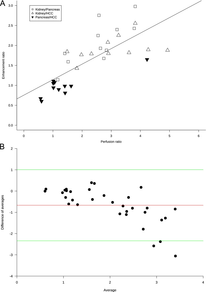
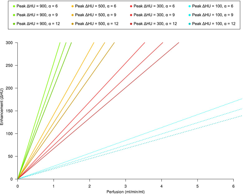
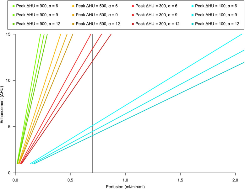
Results: Perfusion values from the two methods were linearly related (r2 = 0.92, p < 0.001; Bland-Altman analysis bias -0.12). The mathematical model showed that the perfusion ratio of two ROIs with the same feeding vessel (aorta) corresponds to their peak enhancement ratio (r2 = 0.55, p < 0.001; Bland-Altman analysis bias -0.68). The relationship between perfusion and tissue enhancement is predicted to be linear in the clinical range of interest, being only function of perfusion, peak feeding vessel enhancement, and bolus shape.

Conclusions: This proof-of-concept study showed that perfusion values of HCC, kidney, and pancreas could be computed using enhancement measured only with two CT scan phases, if aortic peak enhancement and bolus shape are known.

Keywords: Carcinoma (hepatocellular); Contrast media; Perfusion imaging; Tomography (x-ray computed).


Conflict of interest statement

Massimo Cressoni, Paolo Cadringher, Paolo Vitali, Gianpaolo Basso, and Davide Ippolito all declare that they have no conflict of interest related to the present work.

Simone Schiaffino received travel support from Bracco Imaging and is a member of the speakers’ bureau for General Electric Healthcare.

Francesco Sardanelli received research grants from—and is a member of the speakers’ bureau of—General Electric Healthcare, Bayer, and Bracco; he is also member of the Bracco Advisory Group.

Andrea Cozzi and Simone Schiaffino are members of the Editorial Board of European Radiology Experimental, while Francesco Sardanelli is the Editor-in-Chief of European Radiology Experimental: none of them were involved in any way in the revision/decision process, which was entirely managed by the Deputy Editor, Prof. Akos Varga-Szemes (Medical University of South Carolina, Charleston, SC, USA).

Figures

Fig. 1
Fig. 1
ROIs drawn to compute the time-enhancement curves. In A, a ROI on the pancreas was drawn on the largest pancreatic portion included in the CT study volume. While this portion is usually represented by the pancreatic head, in this case the pancreatic head was not included in the study volume due to a pathologic lymph node and the ROI was drawn on the pancreatic tail. B ROI drawn on an HCC focus. C ROI drawn on the cortex of the right kidney. D ROI drawn in the aorta, between the emergency of the superior mesenteric artery and of the renal arteries
Fig. 2
Fig. 2
A Scatterplot and linear regression of the relationship between the two methods of perfusion measurement. Values on the x-axis represent organ perfusion computed using the maximal upslope of the time-enhancement curve using all data points smoothed with a spline function. Values on the y-axis indicate organ perfusion interpolated using the maximal upslope of the gamma variate function using peak tissue enhancement and time-enhancement curve shape parameter (α) computed from the aortic curve. Regression equation: gammavariatebasedperfusionmlming=0.06+0.91×splinebasedperfusion, r2 = 0.92, p < 0.001. Three points for each patient are included: empty squares for the pancreas, empty triangles for the kidney, and black upside-down triangles for hepatocellular carcinoma (HCC). B Bland–Altman plot for the comparison of the two perfusion computation methods. The red line indicates the bias (-0.12), while green lines indicate the lower (-0.73) and upper (0.49) limit of agreement. Only one outlier was observed
Fig. 3
Fig. 3
A Scatterplot and linear regression of the relationship between ratio of perfusions and peak enhancement ratios. Three points for each patient are included: empty squares for kidney/pancreas data, empty triangles for kidney/hepatocellular carcinoma (HCC) data, and black upside-down triangles for pancreas/HCC data. Regression equation: enhancementratio=0.75+0.39×perfusionratio, r2 = 0.55, p < 0.001. Perfusion data refer to the perfusions computed as maximal upslope of the time-enhancement curve obtained using all data points smoothed with the spline function. B Bland–Altman plot for the comparison between enhancement and perfusion ratios, showing a -0.68 bias (red line), with green lines indicating the lower (-2.34) and upper (1.01) limit of agreement
Fig. 4
Fig. 4
Relationship between peak arterial phase tissue enhancement (peak ΔHU) and organ perfusion (mL/s/mL) in a parenchymatous organ with a tmax of approximately 35 s for different peak feeding vessel enhancements and α parameters. To estimate peak arterial phase tissue enhancement, we assumed that contrast medium, injected in a peripheral vein or in a central venous catheter, is diluted by the right and left heart into the whole cardiac output before entering arterial circulation. Assuming a negligible total volume change due to contrast agent injection, if we inject 1.25 mL/kg of a iodinated contrast agent with a 350 mgI/mL concentration at 3.2 mL/s flow rate in a 80 kg man with an average cardiac output of 5000 mL/min (approximately 83 mL/s) and we acquire a CT scan at 120 kVp (with a constant of 26.18 for ΔHU calculation), peak ΔHU will then be 3.2×350×26.1883=350HU
Fig. 5
Fig. 5
Relationship between peak arterial phase tissue enhancement (ΔHU) and organ perfusion (mL/s/mL) in the brain for different peak feeding vessel enhancements and α parameters. Due to the effect of the blood–brain barrier and to the lack of an interstitial phase, we have a very short tmax (approximately 9 s). The average perfusion value for the grey matter (indicated by the black vertical line) would be 0.72 mL/min/mL (range 0.64–0.84 mL/min/mL)
Fig. 6
Fig. 6
Relationship between α and k in the clinical range of α (3–15). In this case, k=1.502+0.092016×α, with r2 = 0.99, p < 0.001

References

    1. García-Figueiras R, Goh VJ, Padhani AR, et al. CT perfusion in oncologic imaging: a useful tool? AJR Am J Roentgenol. 2013;200:8–19. doi: 10.2214/AJR.11.8476. - DOI - PubMed
    1. Kim SH, Kamaya A, Willmann JK. CT perfusion of the liver: principles and applications in oncology. Radiology. 2014;272:322–344. doi: 10.1148/radiol.14130091. - DOI - PMC - PubMed
    1. Ippolito D, Querques G, Okolicsanyi S, et al. Dynamic contrast enhanced perfusion CT imaging: a diagnostic biomarker tool for survival prediction of tumour response to antiangiogenetic treatment in patients with advanced HCC lesions. Eur J Radiol. 2018;106:62–68. doi: 10.1016/j.ejrad.2018.07.012. - DOI - PubMed
    1. Vilela P, Rowley HA. Brain ischemia: CT and MRI techniques in acute ischemic stroke. Eur J Radiol. 2017;96:162–172. doi: 10.1016/j.ejrad.2017.08.014. - DOI - PubMed
    1. Greenberg ED, Gobin YP, Riina H, et al. Role of CT perfusion imaging in the diagnosis and treatment of vasospasm. Imaging Med. 2011;3:287–297. doi: 10.2217/iim.11.19. - DOI - PMC - PubMed