. 2022 Sep 1;13(1):5131.
doi: 10.1038/s41467-022-31410-4.

A compact cold-atom interferometer with a high data-rate grating magneto-optical trap and a photonic-integrated-circuit-compatible laser system

Affiliations

A compact cold-atom interferometer with a high data-rate grating magneto-optical trap and a photonic-integrated-circuit-compatible laser system

Jongmin Lee et al. Nat Commun. .

Abstract

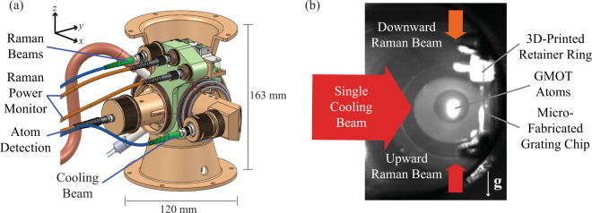
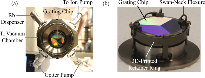
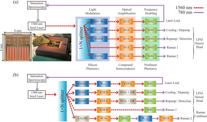
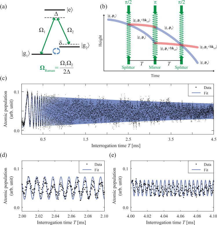
The extreme miniaturization of a cold-atom interferometer accelerometer requires the development of novel technologies and architectures for the interferometer subsystems. Here, we describe several component technologies and a laser system architecture to enable a path to such miniaturization. We developed a custom, compact titanium vacuum package containing a microfabricated grating chip for a tetrahedral grating magneto-optical trap (GMOT) using a single cooling beam. In addition, we designed a multi-channel photonic-integrated-circuit-compatible laser system implemented with a single seed laser and single sideband modulators in a time-multiplexed manner, reducing the number of optical channels connected to the sensor head. In a compact sensor head containing the vacuum package, sub-Doppler cooling in the GMOT produces 15 μK temperatures, and the GMOT can operate at a 20 Hz data rate. We validated the atomic coherence with Ramsey interferometry using microwave spectroscopy, then demonstrated a light-pulse atom interferometer in a gravimeter configuration for a 10 Hz measurement data rate and T = 0-4.5 ms interrogation time, resulting in Δg/g = 2.0 × 10⁻⁶. This work represents a significant step towards deployable cold-atom inertial sensors under large amplitude motional dynamics.


Conflict of interest statement

The authors declare no competing interests.

Figures

Fig. 1
Fig. 1. Concept of the compact light-pulse atom interferometer (LPAI) for high-dynamic conditions.
a 3D rendering of the compact LPAI sensor head with fixed optical components and reliable optomechanical design. b Picture of the steady-state GMOT atoms in the sensor head.
Fig. 2
Fig. 2. Images of the custom Ti vacuum package and the in-vacuum mounted grating chip.
a View of the vacuum package looking at the grating chip through the GMOT cooling beam entry window (≈19 mm clear aperture). The external dimensions of a truncated Ti cube are approximately 40.64 × 40.64 × 40.64 mm3. Also visible are Ti tubes which house the rubidium dispensers, getters, and a brazed connection to the Cu exhaust port. b Close-up view of the in-vacuum grating chip and mount prior to being laser-welded to the vacuum package. The grating chip is held in place with 3D-printed swan-neck flexure mounts.
Fig. 3
Fig. 3. Cross-sectional renderings of the LPAI sensor head.
a Horizontal cross-section showing the cooling-beam and atom-detection channels with fixed optical components. The cooling-channel light is delivered to the sensor head via a polarization maintaining (PM) fiber from which a large collimated Gaussian beam (D1/e228mm) is used for cooling. The beam is truncated to ≈ 19 mm-diameter through the fused silica viewport in the compact LPAI sensor head. The light then passes through a polarizer and a λ/4 waveplate before illuminating the grating chip. The GMOT atoms (solid red circle) form ≈ 3.5 mm from the grating surface. The atom-detection channel was designed to measure atomic fluorescence through a multimode-fiber-coupled avalanche photodiode (APD) module. b Vertical cross-section of the sensor head showing the designed beam paths for Doppler-sensitive Raman. Cross-linearly-polarized Raman beams are launched from the same PM fiber and the two components are split by a polarizing beam splitter (PBS). Fixed optics route the Raman beams to the GMOT atoms (solid red circle) with opposite directions. Note: The data of Figs. 7b and 8 were measured with free-space Raman beam optics.
Fig. 4
Fig. 4. The laser architecture of the LPAI with a single seed laser and time-multiplexed frequency shifting.
a PIC-based laser system composed of silicon photonics for light modulation, compound semiconductor for optical amplification, and nonlinear photonics for frequency doubling towards a co-packaged laser system and a single hybrid-integrated PIC laser system. (Inset-Left) This image is a four-channel silicon photonic SSBM chip with dual-parallel Mach-Zehnder modulators, simultaneously developed at Sandia. This PIC chip (8 × 8 mm2) includes 17 silicon photonic phase modulators (4 for each SSBM), variable optical attenuators, thermo-optic phase shifters, optical filters, and photo detectors. (Inset-Right) This image is a fully packaged silicon photonic SSBM, which has been used to generate the Raman beams from a laser in an LPAI demo. SSBM, single sideband modulator; ΦMOD, phase modulator; SOA, semiconductor optical amplifier; SHG, second harmonic generator. Each channel in the silicon photonics includes a VOA to control the amplitude of the light, and an SOA can function as an optical switch. b PIC-compatible laser system based on discrete components used for the data shown in this paper. f-AOM, fiber-coupled acousto-optic modulator; EDFA, erbium doped fiber amplifier; VOA, variable optical attenuator; SW, optical switch. For Raman 2, we used a f-AOM at 1560 nm and a ΦMOD at 780 nm, which can be replaced with a SSBM at 1560 nm similar to the PIC-based laser system. The f-AOM is used for the phase lock by continuously monitoring the beat note between the two Raman beams. Fig. 10 shows the beat note measurement and the switching of the Raman beams.
Fig. 5
Fig. 5. Optical frequency and timing diagram for the PIC-compatible laser system.
a Optical transitions of 87Rb atoms (D2 transition) for LPAI operation. Cooling, Detection, Depump, and Raman 1 beams use F=2 to F=1,2,3 transitions (Left peaks), and Repump and Raman 2 beams use F=1 to F=0,1,2 transitions (Right peaks). The 1560 nm seed laser is frequency-doubled to 780 nm and locked to F=2 to F=2,3 crossover transition with ~1.15 GHz red-detuning from the F=2F=3 resonance, which is also used for Raman 1. b Diagram of the timing sequence for LPAI operation highlighting important dynamic changes in the laser channels. The pulse width of Repump/Detection/Raman is not to scale.
Fig. 6
Fig. 6. Measurement data rate and loading time of GMOT operation, including sub-Doppler cooling process.
a Plot of atom number versus measurement data rate of GMOT operation. b Plot of atom number versus MOT loading time. Error bars are standard deviation.
Fig. 7
Fig. 7. Ramsey interferometry (π2Tπ2) of sub-Doppler cooled GMOT atoms at the compact LPAI sensor head.
a The atomic fringe of Ramsey interferometry versus microwave detuning from atomic resonance (ωHF/2π). The interrogation time T is 450 μs, resulting in a fringe spacing of δωRamsey/2π ≃ 2.27 kHz. The measurement data rate is 13.33 Hz. b The atomic fringe of Ramsey interferometry versus Doppler-free Raman detuning from atomic resonance (ωHF/2π). The interrogation time T is 48.08 μs, resulting in a fringe spacing of δωRamsey/2π ≃ 19.74 kHz. The measurement data rate is 10 Hz. Both plots are based on a single shot-to-shot measurement.
Fig. 8
Fig. 8. Atom interferometry of sub-Doppler cooled GMOT atoms in the compact LPAI sensor head.
a Three-level atomic system for stimulated Raman transitions. g1=F=1,mF=0, ground state 1; g2=F=2,mF=0 ground state 2; e, excited state; Δ, single-photon detuning; δ, two-photon detuning which depends on the Doppler shift; ΩRaman, effective Rabi frequency of Raman beams; Ω1, single-photon Rabi frequency of g1e transition; Ω2, single-photon Rabi frequency of g2e transition. b Space-time trajectory of atomic wavepackets during LPAI. A three-light-pulse sequence, π2TπTπ2, coherently addresses the ground states of the atoms and provides the state-dependent momentum kicks, ℏkeff ≈ 2ℏk, where p0 is the initial atomic momentum; T, the free-evolution time between Raman pulses; keff, the effective wavenumber of stimulated Raman transition; k, the wavenumber (2π/λ) of a single Raman beam. c Scan of the interrogation time showing the LPAI chirped fringe for T = 0.0 ms to 4.5 ms. The fringe chirping results from the Doppler shift of the cold atoms relative to the Raman beams as the atoms accelerate due to gravity. Each data point in the plot is an average of three data points and a slowly-varying offset was removed. The data is fit to a chirped sinusoidcoskeffgkT2+τπ(1+2π)T+ϕ0, where τπ is the π-pulse duration, gk is gravity, and ϕ0 is an arbitrary phase factor. We measured g = 9.79316(2)ms−2 with the statistical uncertainty of Δg/g = 2.0 × 10−6 without vibration isolation. Plots (d) and (e) provide a detailed view of the chirped fringe of (c) for T = 2.0 ms to 2.1 ms and T = 4.0 ms to 4.1 ms, respectively. The measurement data rate is 10 Hz.
Fig. 9
Fig. 9. Grating design and fabrication process.
a Schematic of the hexagonal grating chip showing a side-to-side length of 17.5 mm and three grating areas symmetrically arranged in the circular shape. The non-grating flat edges are used for the grating retainer clips. The 1/e2 beam diameter of the cooling beam is 28 mm truncated to ≈19 mm by the fused silica viewport. b Fabrication process of the GMOT grating chip. Parameters for the grating chip used in this paper are tAl = 50nm, tSiO2 = 195 nm, d = 1.2 μm, and ~ 50% duty cycle (details in main text).
Fig. 10
Fig. 10. Optical setup for combining the two 780 nm Raman channels with crossed-linear-polarization and phase locking.
Approximately 10% of the combined power is diverted for phase locking while the remaining power is directed towards an acousto-optic modulator for pulsing. The combined Raman beams are coupled into the same polarization maintaining fiber with the polarizations aligned to the slow and fast axes of the fiber. PBS polarizing beam splitter, R90:T10, non-polarizing cube beam splitter; Pol. polarizer, AOM acousto-optic modulator.

References

    1. Heavner TP, et al. First accuracy evaluation of NIST-F2. Metrologia. 2014;51:174–182. doi: 10.1088/0026-1394/51/3/174. - DOI
    1. Wynands R, Weyers S. Atomic fountain clocks. Metrologia. 2005;42:S64–S79. doi: 10.1088/0026-1394/42/3/S08. - DOI
    1. Nicholson TL, et al. Systematic evaluation of an atomic clock at 2 × 10⁻¹⁸ total uncertainty. Nat. Comm. 2015;6:1. - PMC - PubMed
    1. Ludlow AD, Boyd MM, Ye J, Peik E, Schmidt PO. Optical atomic clocks. Rev. Mod. Phys. 2015;87:637–701. doi: 10.1103/RevModPhys.87.637. - DOI
    1. Dang HB, Maloof AC, Romalis MV. Ultrahigh sensitivity magnetic field and magnetization measurements with an atomic magnetometer. App. Phys. Lett. 2010;97:151110. doi: 10.1063/1.3491215. - DOI