Review
. 2022 Aug 31;39(3):234-247.
doi: 10.1055/s-0042-1751295. eCollection 2022 Jun.

Percutaneous Chest Tube for Pleural Effusion and Pneumothorax

Affiliations
Review

Percutaneous Chest Tube for Pleural Effusion and Pneumothorax

Ifechi Ukeh et al. Semin Intervent Radiol. .

Abstract

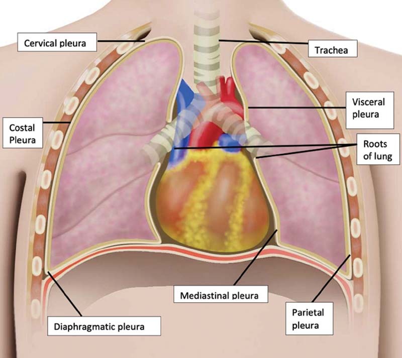
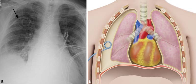
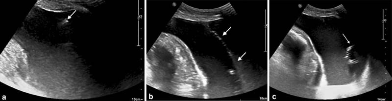
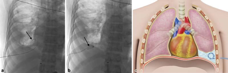
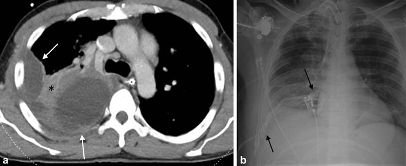
Chest tubes are placed in the pleural space to evacuate abnormal fluid or air accumulations. Various types and sizes of chest tubes are available. Imaging including ultrasound, computed tomography, and fluoroscopy should be used to guide chest tube placement. Understanding the anatomy of the pleural space, along with the etiology and classification of pleural space disease, can help optimize chest tube management. This article will review the indications, contraindications, techniques, and postprocedure follow-up of chest tube placement as well as discuss the management and prevention of complications.

Keywords: interventional radiology; percutaneous chest tube; pleural drain; pleural effusion; pneumothorax; thoracostomy tube.


Conflict of interest statement

Conflict of Interest None declared.

Figures

Fig. 1
Fig. 1
Anatomy of the pleural space. Pleura consists of a layer of simple squamous cells supported by connective tissue. The visceral pleura lines the lungs and the parietal pleura lines the thoracic cavity. These two parts are continuous and the transition from visceral pleura to parietal pleura occurs at the root of each lung. The parietal pleura can be subdivided into mediastinal, cervical, costal, and diaphragmatic pleura.
Fig. 2
Fig. 2
A flowchart for the classification of pneumothorax. COPD, chronic obstructive pulmonary disease.
Fig. 3
Fig. 3
A 76-year-old man with a history of atrial fibrillation and severe mitral regurgitation status post cardiac surgery complicated by pneumothorax. ( a ) Frontal chest radiograph demonstrates an apically directed 12-Fr chest tube (arrow) placed under fluoroscopic guidance. ( b ) Illustration of chest tube placement directed apically for pneumothorax.
Fig. 4
Fig. 4
A 66-year-old woman with fever and large complicated parapneumonic effusion requiring urgent chest tube placement for source control. ( a ) Gray scale ultrasound demonstrates free flowing pleural fluid. 5-Fr Yueh catheter (arrow) used to access the pleural space. ( b ) Ultrasound guidance was used to visualize guidewire (arrows) positioning in the pleural cavity and dilation was performed over the guidewire. ( c ) Ultrasound immediately after 12-Fr chest tube placement shows the catheter pigtail (arrow) in the appropriate position.
Fig. 5
Fig. 5
A 74-year-old man with a history of hypertension and diabetes presenting with shortness of breath was found to have a large right pleural effusion on imaging. ( a ) Fluoroscopic guidance was used to place a single wall needle into the right pleural space with prompt return of straw-colored fluid. The guidewire (arrow) was advanced into the pleural space under fluoroscopy. ( b ) An 8.5-Fr pigtail catheter (arrow) was advanced over the guidewire with the pigtail formed in the lung base. The catheter was connected to a Pleur-evac set to −20 cm of water suction.( c ) Illustration of chest tube placement directed inferiorly for pleural effusion.
Fig. 6
Fig. 6
A 43-year-old patient with acute high-speed motor vehicle trauma. ( a ) Axial CT of the chest with loculated right basilar fluid collections (white arrows) and adjacent parenchymal consolidation (asterisk) that was indistinguishable on sonography requiring CT-guided placement. ( b ) Frontal chest radiograph demonstrates two 10-Fr pigtail chest tubes (black arrows) placed within the loculated collections.
Fig. 7
Fig. 7
( a ) Illustration of a wet suction three-chamber chest drainage system. Pleural fluid drained by the chest tube will accumulate in the fluid collection chambers (yellow arrows). Air from the pleural space (black arrows) drained by the chest tube will flow into the water seal chamber and bubbling will be visualized in the air leak window. The suction port can be connected to wall suction. Atmospheric air (blue arrows) is drawn into the suction control chamber to regulate the amount of suction. ( b ) Image of a dry suction Pleur-evac three-chamber system. Note the dry suction regulator that controls the level of suction between −10 and −40 cm.
Fig. 8
Fig. 8
Illustration of a Heimlich valve. ( a ) The valve consists of a rigid outer chamber and an internal collapsible rubber valve. The inlet nozzle connects directly to the chest tube and the outlet nozzle can be left open or connected to a collection bag. ( b ) Positive pressure is created within the chamber when air flows through the inlet nozzle from the chest tube. This distends the rubber valve allowing air to exit through the outlet nozzle. ( c ) During inhalation, negative pressure is created in the chamber causing the rubber valve to collapse and prohibits air reentry through the rubber valve.
Fig. 9
Fig. 9
A 22-year-old woman with no underlying lung disease presenting with shortness of breath and chest pain. ( a ) Frontal radiograph demonstrates a primary spontaneous pneumothorax (arrow). ( b ) ThoraVent catheter (UreSil Corporation, Skokie, IL) (arrow) was placed in the fourth intercostal space, midclavicular line under fluoroscopic guidance, and the patient was discharged with outpatient follow-up. ( c ) Frontal radiograph of the next day demonstrated stable position of the ThoraVent (black arrow) with intrapleural catheter (white arrow) and significant reduction in the size of the pneumothorax.
Fig. 10
Fig. 10
A 65-year-old man with known interstitial lung disease and history of probable oxaliplatin pneumonitis. ( a ) Axial CT, lung window, demonstrates moderate right pneumothorax (arrow) with underlying moderate bilateral fibrosis and background emphysema. ( b ) Axial lung window demonstrates persistent pneumothorax following CT-guided placement of a 10-Fr pigtail chest tube (black arrow) consistent with trapped lung.
Fig. 11
Fig. 11
A 51-year-old man status-post US-guided liver biopsy complicated by intercostal artery bleeding and hemothorax requiring 24-Fr chest tube insertion by blunt dissection at bedside. ( a ) Aortogram demonstrates active contrast extravasation from the 9th intercostal artery (black arrow) secondary to liver biopsy and from the 8th intercostal artery (white arrow) secondary to chest tube placement. ( b ) Selective 8th intercostal arteriogram demonstrates active bleeding (white arrow) adjacent to the site of tube insertion. ( c ) Post embolization angiogram of the 8th intercostal artery demonstrates hemostasis. Note coils (black arrows) at both sites of previously identified active bleeds.
Fig. 12
Fig. 12
A 67-year-old man presenting with blunt trauma to the chest. ( a ) Frontal radiograph shows persistent moderate apical pneumothorax (white arrow) with 10-Fr chest tube (black arrow) projecting over the lung apex. Chest tube was placed at the bedside without image guidance. ( b ) Axial CT of the chest obtained to evaluate persistent pneumothorax demonstrates the chest tube (white arrow) terminating in the right anterior extrathoracic soft tissues with surrounding subcutaneous emphysema (black arrow) consistent with malpositioning.
Fig. 13
Fig. 13
An 86-year-old woman with a history of atrial fibrillation and well-differentiated squamous cell carcinoma of the anterior mandible. ( a ) Axial CT of the chest demonstrates a large right pleural effusion (star) with complete collapse of the right lung. ( b ) Axial CT of the chest demonstrates 14-Fr pigtail catheter (arrow) with significant decreased pleural effusion after drainage of 2.5 L of fluid. ( c ) Axial CT the next day demonstrates residual pleural effusion with diffuse patchy consolidations, ground-glass opacities, and septal thickening due to reexpansion pulmonary edema (compare with normal left lung).

Similar articles

References

    1. Albertine K H, Wiener-Kronish J P, Bastacky J, Staub N C. No evidence for mesothelial cell contact across the costal pleural space of sheep. J Appl Physiol (1985) 1991;70(01):123–134. - PubMed
    1. Kookoolis A S, Puchalski J T, Murphy T E, Araujo K L, Pisani M A. Mortality of hospitalized patients with pleural effusions. J Pulm Respir Med. 2014;4(03):184. - PMC - PubMed
    1. Light R W, Macgregor M I, Luchsinger P C, Ball W C., Jr Pleural effusions: the diagnostic separation of transudates and exudates. Ann Intern Med. 1972;77(04):507–513. - PubMed
    1. Vives M, Porcel J M, Vicente de Vera M, Ribelles E, Rubio M. A study of Light's criteria and possible modifications for distinguishing exudative from transudative pleural effusions. Chest. 1996;109(06):1503–1507. - PubMed
    1. Blackmore C C, Black W C, Dallas R V, Crow H C. Pleural fluid volume estimation: a chest radiograph prediction rule. Acad Radiol. 1996;3(02):103–109. - PubMed