. 2022 Sep 9;8(36):eabp8738.
doi: 10.1126/sciadv.abp8738. Epub 2022 Sep 9.

Super-resolution wearable electrotactile rendering system

Affiliations

Super-resolution wearable electrotactile rendering system

Weikang Lin et al. Sci Adv. .

Abstract

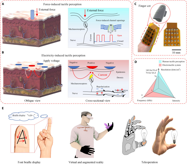
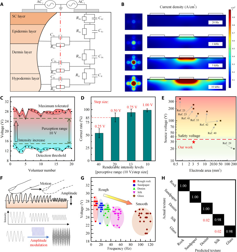
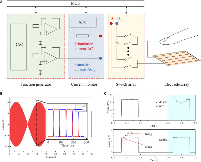
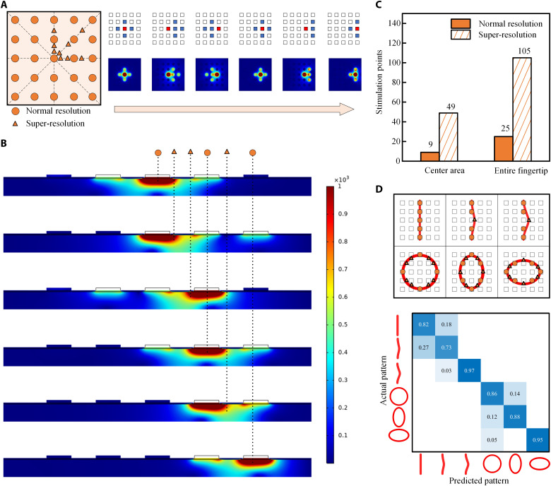
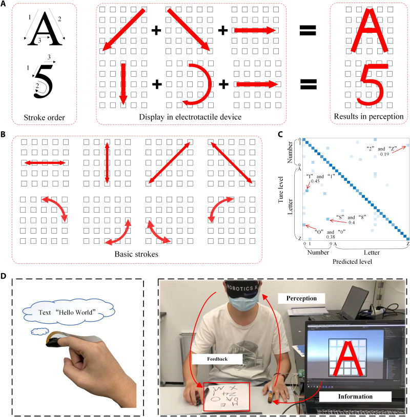
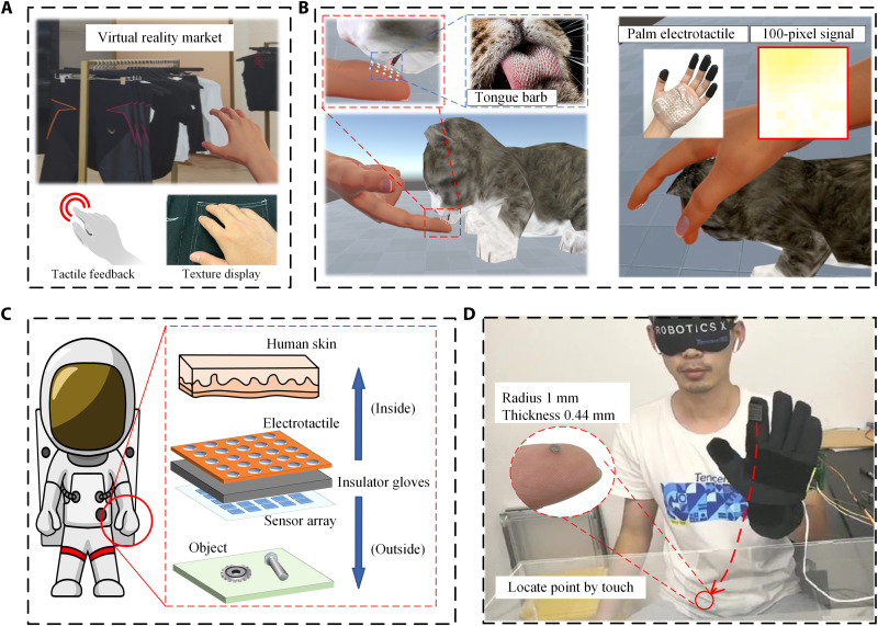
The human somatosensory system is capable of extracting features with millimeter-scale spatial resolution and submillisecond temporal precision. Current technologies that can render tactile stimuli with such high definition are neither portable nor easily accessible. Here, we present a wearable electrotactile rendering system that elicits tactile stimuli with both high spatial resolution (76 dots/cm2) and rapid refresh rates (4 kHz), because of a previously unexplored current-steering super-resolution stimulation technique. For user safety, we present a high-frequency modulation method to reduce the stimulation voltage to as low as 13 V. The utility of our high spatiotemporal tactile rendering system is highlighted in applications such as braille display, virtual reality shopping, and digital virtual experiences. Furthermore, we integrate our setup with tactile sensors to transmit fine tactile features through thick gloves used by firefighters, allowing tiny objects to be localized based on tactile sensing alone.


Figures

Fig. 1.
Fig. 1.. Design and architecture of the electrotactile rendering system.
(A) Schematic of the tactile perception of human skins: Strain on the skin induced by an external force triggers the mechanosensitive channels that convert external force into electrochemical and electrical signals. (B) Schematic of the electrotactile system whereby current is induced in the skin to stimulate mechanoreceptors and nerves, generating action potentials that are interpreted as tactile signals by the brain. (C) Optical images of the electrotactile device, an FPC with 25 half-sphere electrodes attached in a rubber finger cot. (D) Comparison between human tactile perception and the electrotactile rendering device in spatial resolution, refresh rates, and intensity range. (E) Demonstrations of the electrotactile system in braille display, VR and augmented reality, and teleoperation.
Fig. 2.
Fig. 2.. The simulation and experimental results of electrical stimulation using high-frequency AC.
(A) Schematic illustration of electrical impedance model and equivalent circuit of the human skin. SC, stratum corneum. (B) Simulation results of current density distribution at different frequencies. (C) Relationship between tactile perception intensity and stimulation voltage; as the voltage increases, the intensity gradually increases from a slight touch to a sharp prick. Error bars indicate the fluctuation of the test results of each volunteer in multiple measurements. (D) Ability of the electrotactile system to render different tactile intensities. The number of renderable intensity levels can be changed by adjusting the step size of each changed voltage. Users can feel 20 different intensity levels with 85% accuracy. Error bars show the SD between 20 volunteers. (E) Comparison of the applied voltage and electrode areas in this work with other electrotactile devices. (F) Illustration of the roughness perception, which is mainly determined by intensity and vibration frequency. (G) Relationship between the roughness perception and stimulation voltage and frequency. (H) Classification confusion matrix of five different roughness surfaces.
Fig. 3.
Fig. 3.. The structure of the electrotactile rendering system.
(A) Schematic diagram of the control system, which consists of three parts. Function generator generates the desired stimulation current AC1 and AC2, current monitor ensures the consistency of output perception by feedback control, and switch array manages the state of each electrode separately. ADC, analog-to-digital converter. (B) Waveform of the stimulation current. Ten kilohertz of square wave is amplitude-modulated by 40-Hz sine wave. (C) Stable electrotactile perception under the feedback control strategy, where the stimulation voltage is changed according to the measured current.
Fig. 4.
Fig. 4.. Beam-forming super-resolution control strategy.
(A) Illustration of the 5 × 5 electrotactile device rendering resolution (left) and the top view of simulation results of current density under the different distribution of stimulation electrodes (right). The 25 squares represent the actual distribution of electrodes, in which the red, blue, and blank represent the states of the electrodes in AC1, AC2, and floating, respectively. (B) Cross-sectional view of simulation results of current density under the different distribution of stimulation electrodes. (C) Improvement of tactile rendering resolution under the super-resolution strategy. (D) Schematic of different patterns of rendering strategy and these patterns’ recognition confusion matrix, where the circle dot means normal resolution site and the triangle dot is super-resolution site.
Fig. 5.
Fig. 5.. Font braille strategy for letters and numbers display.
(A) Stroke order of alphabet “A” and number “5” and its control strategy of the tactile rendering based on the font braille strategy. (B) Sixteen kinds of basic stroke order in the font braille strategy. (C) Confusion matrix of the English alphabet and numbers. Some among them would still be confused such as “I” and “1,” “S” and “8,” “O” and “0,” and “2″ and “Z”. (D) Schematic (left) and demonstration (right) of text information transmission through the electrotactile device.
Fig. 6.
Fig. 6.. Applications of the electrotactile rendering system.
(A and B) Examples of the electrotactile in virtual and augmented reality. (A) Feeling the touch and texture of clothes in VR shopping. (B) Touch communication with a virtual cat to feel a sense of itchy in the finger and enjoy the touch feeling of petting cat through the palm electrotactile device. (C) Illustration of tactile restoring for astronauts carrying out crucial tasks. The sensor array is attached outside of the glove to sense the object, and the electrotactile device is attached inside to render the tactile information. (D) Demonstration of fast and precise positioning of a tiny part while wearing a thick protective glove by electrotactile rendering system.

References

    1. Chen H. W., Lee J. H., Lin B. Y., Chen S., Wu S. T., Liquid crystal display and organic light-emitting diode display: Present status and future perspectives. Light Sci. Appl. 7, 17168 (2018). - PMC - PubMed
    1. Huang Y., Hsiang E. L., Deng M. Y., Wu S. T., Mini-LED, micro-LED and OLED displays: Present status and future perspectives. Light Sci. Appl. 9, 105 (2020). - PMC - PubMed
    1. Zhu J., Liu X., Shi Q., He T., Sun Z., Guo X., Liu W., Sulaiman O. B., Dong B., Lee C., Development trends and perspectives of future sensors and MEMS/NEMS. Micromachines 11, 7 (2020). - PMC - PubMed
    1. Lee W. W., Tan Y. J., Yao H., Li S., See H. H., Hon M., Ng K. A., Xiong B., Ho J. S., Tee B. C. K., A neuro-inspired artificial peripheral nervous system for scalable electronic skins. Sci. Robot. 4, eaax2198 (2019). - PubMed
    1. Sundaram S., Kellnhofer P., Li Y., Zhu J. Y., Torralba A., Matusik W., Learning the signatures of the human grasp using a scalable tactile glove. Nature 569, 698–702 (2019). - PubMed