Review
. 2022 Jul 21;13(31):8924-8941.
doi: 10.1039/d2sc01786e. eCollection 2022 Aug 10.

Fabrication of graphene-based porous materials: traditional and emerging approaches

Affiliations
Review

Fabrication of graphene-based porous materials: traditional and emerging approaches

Heidi Jahandideh et al. Chem Sci. .

Abstract

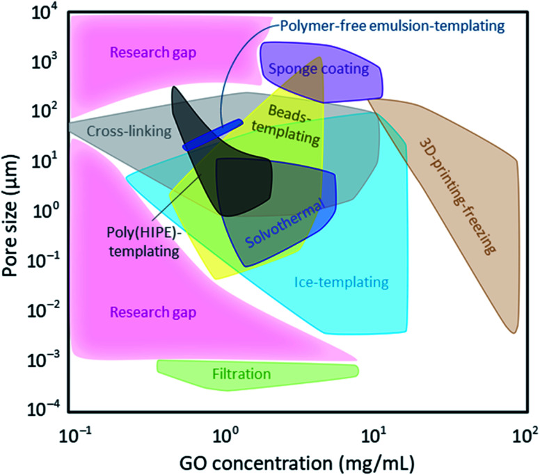
The anisotropic nature of 'graphenic' nanosheets enables them to form stable three-dimensional porous materials. The use of these porous structures has been explored in several applications including electronics and batteries, environmental remediation, energy storage, sensors, catalysis, tissue engineering, and many more. As method of fabrication greatly influences the final pore architecture, and chemical and mechanical characteristics and performance of these porous materials, it is essential to identify and address the correlation between property and function. In this review, we report detailed analyses of the different methods of fabricating porous graphene-based structures - with a focus on graphene oxide as the base material - and relate these with the resultant morphologies, mechanical responses, and common applications of use. We discuss the feasibility of the synthesis approaches and relate the GO concentrations used in each methodology against their corresponding pore sizes to identify the areas not explored to date.


Conflict of interest statement

N. T. holds a patent on the use of graphene sponges for water treatment. All other authors have no conflicts to declare.

Figures

Fig. 1
Fig. 1. (a) Publications on the use of porous graphene-based materials in various applications. Data obtained from Web of Science using the search query: “TI = ((porous OR aerogel OR hydrogel OR sponge* OR scaffold*) AND graphene). The size of each segment in the donut chart correlates to the number of publications with the assigned colour code. (b) Classification of methods studied in this review.
Fig. 2
Fig. 2. (a) Schematic illustration of a typical solvothermal process. GO sheets are randomly oriented when dispersed in proper solvent but self-assemble upon their reduction into rGO and form a hierarchically porous material. The molecules surrounding the rGO nanosheets are water molecules. Schematic is not to scale. (b) Higher GO content yields a larger rGO sponge, as expected, and a longer reduction reaction time reduces the nanosheets further, leading to a smaller more stacked and less porous sponge. (c) The smaller the sheets' sizes, the smaller the pore sizes are in a porous graphene-based material. (b) is adapted with permission from ref. 38 © 2010 American Chemical Society. SEM images in (c) are adapted with permission from ref. 41 © 2016 Royal Society of Chemistry.
Fig. 3
Fig. 3. (a) Schematic illustration of a filtration setup showing the randomness of and the distance between GO sheets. Once filtered, the nanosheets self-assemble into stacked porous 3D films. (b) SEM micrographs of a GO/alginate film prepared by means of evaporation. As displayed, higher GO content results in a more stacked and less porous 3D film. SEM images are adapted with permission from ref. 39 © 2019 American Chemical Society.
Fig. 4
Fig. 4. Typical schematic representations of: (left) a physical cross-linking between a polyacrylamide (PAM) chain and a GO nanosheet originating solely from intermolecular interactions such as hydrogen bonding, and (right) a chemical cross-linking between a PAM molecule and a GO nanosheet which is a consequence of covalent bonding.
Fig. 5
Fig. 5. (a) Schematic illustration of a bulk freeze-drying process. As shown here, ice crystals begin to form close to the container's walls and grow in random directions. (b) SEM micrographs of a bulk lyophilized GO-based aerogel, showing the randomness of pore architecture as a result of randomly formed ice crystals. Please note the insets in SEM images show the viewpoint of these porous materials (top vs. side view). (c) Schematic illustration of a unidirectional freeze-drying process. As shown, ice crystals begin to form from the liquid nitrogen side and grow upwards. (d) SEM micrographs of a unidirectionally lyophilized GO-based aerogel consisting of microchannels in the direction of ice crystal formation. (e) Schematic illustration of a bidirectional freeze-drying process. As shown, ice crystals form and grow in two directions: along the axis and radially, due to the usage of a temperature conductive container, such as copper. (f) SEM micrographs of a bidirectionally lyophilized GO-based aerogel display the formation of microchannels with different morphologies than those found in unidirectional freeze-drying. SEM images shown in the bottom row refer to different distances from the centre of the aerogel (regions numbered 1–3 and shown in the schematic). GO nanosheets are found to be more closely assembled near the centre of the aerogel. SEM images in 5b and 5d are adapted with permission from ref. 91 ©2019 American Chemical Society (2019). SEM images in (f) are adapted with permission from ref. 89 © 2018 American Chemical Society.
Fig. 6
Fig. 6. Schematic illustration of a direct ink writing – a type of 3D printing process using GO ink (concentrated dispersion of GO in a solvent). Upon freeze-drying and removal of the solvent, a 3D porous GO aerogel is obtained, with porosity similar to that of freeze-dried aerogels.
Fig. 7
Fig. 7. (a) Photograph of a 3D printed sponge. SEM micrograph showing: (b) T-junction cut from (a), (c) morphology of the sponge along the deposition direction, (d) cross-sectional interfacial region in (c), (e) the top-view of the region in (a), and (f) morphology of the typical pores found in the aerogels. Figure reprinted with permission from ref. 97 © 2016 Wiley-VCH.
Fig. 8
Fig. 8. Schematic illustration of beads' (nanoparticles or microspheres) localization in between nanosheets, creating ordered spacings. Removal of the beads results in formation of a 3D porous film with a porosity similar to the sizes of beads used.
Fig. 9
Fig. 9. Schematic illustration of coating a polymeric porous substrate with GO by simply immersing the substrate into the GO dispersion.
Fig. 10
Fig. 10. Schematic illustration of three different nanomaterials that can be obtained by emulsion-templating: beads (i.e., microspheres), porous media and composites.
Fig. 11
Fig. 11. (a) Schematic illustration of fabricating a 3D interconnected graphene-based porous material by templating a HIPE and polymerizing it into a poly(HIPE). (b) Schematic illustration of fabricating a 3D graphene-based porous material by templating an emulsion without the polymerization step and by reducing GO using vitamin C.
Fig. 12
Fig. 12. Schematic representation of the relationship between the methodologies, GO concentration, and porous sizes of graphene-based porous materials using the available literature data. The pink areas outline the current research gaps.

References

    1. Hu K. Xie X. Cerruti M. Szkopek T. Controlling the shell formation in hydrothermally reduced graphene hydrogel. Langmuir. 2015;31(20):5545. doi: 10.1021/acs.langmuir.5b00508. - DOI - PubMed
    1. Li Y. Cui W. Liu L. Zong R. Yao W. Liang Y. Zhu Y. Removal of Cr(VI) by 3D TiO 2 -graphene hydrogel via adsorption enriched with photocatalytic reduction. Appl. Catal., B. 2016;199:412. doi: 10.1016/j.apcatb.2016.06.053. - DOI
    1. Shen Y. Fang Q. Chen B. Environmental applications of three-dimensional graphene-based macrostructures: adsorption, transformation, and detection. Environ. Sci. Technol. 2015;49(1):67. doi: 10.1021/es504421y. - DOI - PubMed
    1. Zhu C. Liu P. Mathew A. P. Self-Assembled TEMPO Cellulose Nanofibers: Graphene Oxide-Based Biohybrids for Water Purification. ACS Appl. Mater. Interfaces. 2017;9(24):21048. doi: 10.1021/acsami.7b06358. - DOI - PubMed
    1. Surwade S. P. Smirnov S. N. Vlassiouk I. V. Unocic R. R. Veith G. M. Dai S. Mahurin S. M. Water desalination using nanoporous single-layer graphene. Nat. Nanotechnol. 2015;10(5):459. doi: 10.1038/nnano.2015.37. - DOI - PubMed