. 2022 Sep 20;119(38):e2201589119.
doi: 10.1073/pnas.2201589119. Epub 2022 Sep 12.

Anelasticity in thin-shell nanolattices

Affiliations

Anelasticity in thin-shell nanolattices

I-Te Chen et al. Proc Natl Acad Sci U S A. .

Abstract

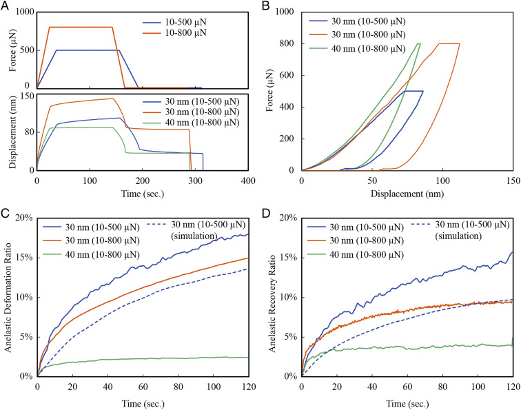
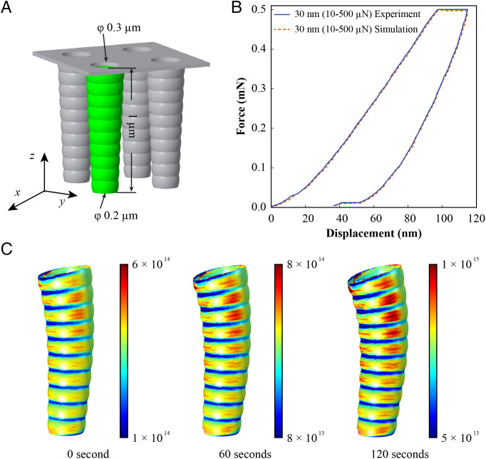
In this work, we investigate the anelastic deformation behavior of periodic three-dimensional (3D) nanolattices with extremely thin shell thicknesses using nanoindentation. The results show that the nanolattice continues to deform with time under a constant load. In the case of 30-nm-thick aluminum oxide nanolattices, the anelastic deformation accounts for up to 18.1% of the elastic deformation for a constant load of 500 μN. The nanolattices also exhibit up to 15.7% recovery after unloading. Finite element analysis (FEA) coupled with diffusion of point defects is conducted, which is in qualitative agreement with the experimental results. The anelastic behavior can be attributed to the diffusion of point defects in the presence of a stress gradient and is reversible when the deformation is removed. The FEA model quantifies the evolution of the stress gradient and defect concentration and demonstrates the important role of a wavy tube profile in the diffusion of point defects. The reported anelastic deformation behavior can shed light on time-dependent response of nanolattice materials with implication for energy dissipation applications.

Keywords: 3D nanostructures; anelasticity; nanoindentation; nanolattices.


Conflict of interest statement

The authors declare no competing interest.

Figures

Fig. 1.
Fig. 1.
Schematic of the indentation test. In Stage I, a load with constant loading rate is applied on the nanolattices and results in elastic deformation and stress gradient in the elements. The load is then held constant to allow the diffusion of the defects across the stress gradient, resulting in the anelastic deformation shown in Stage II. In Stage III the load is removed, and the stress gradient induced by the elastic deformation is removed. This stage is held for an extended amount of time to allow the defect to diffuse back to a uniform profile and enabling the recovery of the anelastic deformation in Stage IV.
Fig. 2.
Fig. 2.
SEM images of the nanolattice cross-sections. (A) Fabrication process of the nanolattices. (B) 30 nm Al2O3 nanolattices. (C) 40 nm Al2O3 nanolattices. (D) 75 nm ZnO nanolattices.
Fig. 3.
Fig. 3.
Nanoindentation results of Al2O3 thin-shell nanolattices. (A) Force and displacement profiles over time of Al2O3 nanolattices. (B) Representative force–displacement indentation profiles. (C) The anelastic deformation ratio αd over time during the holding period (after loading). (D) The anelastic recovery ratio αr over time during the holding period (after unloading). In (C) and (D), the dashed curves are simulation results and all the solid curves are experimental results.
Fig. 4.
Fig. 4.
(A) Nanolattice model in COMSOL with the highlighted tube further analyzed. (B) Comparison between experiment and simulation in force versus displacement curves during nanoindentation. (C) Sequence of images showing tube deformation and defect concentration levels during the holding period from 0 s to 120 s. The unit for the defect concentrations shown is number/m3.
Fig. 5.
Fig. 5.
Defect concentration distribution at different locations. (A) Defect concentration distribution across the tube thickness at A and B sections. (B) Defect concentration along the height of the tube external shell. (C) Defect concentration around the internal and external circumferences of the tube at section A. (D) Defect concentration around the internal and external circumferences of the tube at section B.

References

    1. Gibson L. J., Cellular Solids: Structure and Properties (Cambridge University Press, ed. 2, 1997).
    1. Hamm C. E., et al. , Architecture and material properties of diatom shells provide effective mechanical protection. Nature 421, 841–843 (2003). - PubMed
    1. Wegst U. G. K., Bai H., Saiz E., Tomsia A. P., Ritchie R. O., Bioinspired structural materials. Nat. Mater. 14, 23–36 (2015). - PubMed
    1. Gao H., Ji B., Jäger I. L., Arzt E., Fratzl P., Materials become insensitive to flaws at nanoscale: Lessons from nature. Proc. Natl. Acad. Sci. U.S.A. 100, 5597–5600 (2003). - PMC - PubMed
    1. Aizenberg J., et al. , Skeleton of Euplectella sp.: Structural hierarchy from the nanoscale to the macroscale. Science 309, 275–278 (2005). - PubMed

LinkOut - more resources