Biomechanical study on parallel cannulated compression screw combined with medial buttress plate fixation and F-type cannulated compression screw fixation in Pauwels III femoral neck fracture:A finite element analysis
- PMID: 36097783
- PMCID: PMC10950106
- DOI: 10.11817/j.issn.1672-7347.2022.220022
Biomechanical study on parallel cannulated compression screw combined with medial buttress plate fixation and F-type cannulated compression screw fixation in Pauwels III femoral neck fracture:A finite element analysis
Abstract
Objectives: Pauwels III fracture is a kind of femoral neck fractures, in which the angle of the fracture line in the coronal plane and the upper edge of the acetabulum is more than 50°. Internal fixation for the treatment of femoral neck fractures is largely performed by cannulated compression screw (CCS), dynamic hip screw, or locking plate. This study aims to compare the biomechanical properties of parallel CCS combined with medial buttress plate fixation and F-type CCS fixation in the treatment of Pauwels III femoral neck fracture by finite element modeling and to determinate the most suitable procedure for such fractures.
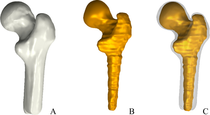
Methods: A 52-year-old male volunteer, 176 cm in height and 72 kg in weight, with no history of hip joint, was selected. X-ray and CT examination confirmed that the morphology and bone condition of the right hip of the volunteer were normal. A simulation model of Pauwels III femoral neck fracture was established from the collected CT data of the right proximal femur of the volunteer by the finite element method. Four internal fixations were developed to treat the finite element model: Three CCSs in an inverted triangular parallel configuration combined with medial buttress plate model served as Group A, 2 CCSs in a vertical parallel configuration combined with medial buttress plate model served as Group B, 2 CCSs in a horizontal parallel configuration combined with medial buttress model served as Group C, and the "F" shaped CCS model served as Group D. The distribution of stress, the peak stress, the distribution and maximum of displacement of internal fixations and fracture ends in different models were evaluated.
Results: For Groups A, B, C, and D, the peak stresses on the internal fixation were 362.74, 586.84, 558.25, and 208.66 mPa, respectively, all of which occurred near the fractures and the stress distribution in Group D was the most uniform. The maximum displacements of internal fixations in Groups A, B, C, and D were 0.39, 0.45, 0.44, and 0.41 mm, respectively; the peak stresses on the fracture ends were 70.62, 98.48, 55.84, and 65.39 mPa, respectively, all of which were concentrated on the base of femoral neck and lateral cortex of the femoral shaft, and the stresses of Groups C and D were more evenly distributed than those of Groups A and B. The maximum displacements of fracture ends in Groups A, B, C, and D were 0.44, 0.52, 0.50, and 0.44 mm, respectively.
Conclusions: The biomechanical stability of F-type CCS fixation is similar to that of 3 CCSs in an inverted triangular parallel configuration combined with medial buttress plate, with a better dispersion of stress. F-type CCS fixation may be a well option for the treatment of femoral neck fracture of Pauwels III.
目的: Pauwels III型股骨颈骨折是指在冠状面上骨折线与髋臼上缘连线的夹角大于50°的股骨颈骨折。临床上较常用的内固定方式为空心加压螺钉(cannulated compression screw,CCS)、动力髋螺钉和锁定钢板。本研究对F型CCS固定和3种平行构型CCS联合内侧支撑钢板钢板固定进行建模和有限元分析,旨在比较4种内固定方式治疗Pauwels III型股骨颈骨折的生物力学特性,为临床治疗提供理论依据。方法: 选取1位52岁男性志愿者,身高176 cm,体重72 kg,无髋关节病史,行髋关节X线片及CT检查证实骨骼形态、骨质条件正常。应用螺旋CT对其右侧股骨近端行连续薄层扫描,采用有限元法利用CT采集的数据建立Pauwels III型股骨颈骨折仿真模型,在模型上比较倒三角平行构型CCS+内侧支撑钢板(A组)、垂直平行构型CCS+内侧支撑钢板(B组)、水平平行构型CCS+内侧支撑钢板(C组)和F型CCS(D组)的内植物、骨折端的应力分布、应力峰值、位移分布及位移峰值。结果: A、B、C、D组模型的内植物应力峰值分别为362.74、586.84、558.25、208.66 mPa,应力峰值均出现在内植物的骨折断端部分,其中D组的应力分布最为均匀;A、B、C、D组内植物位移峰值分别为0.39、0.45、0.44、0.41 mm;骨折端的应力峰值分别为70.62、98.48、55.84、65.39 mPa,断端应力均集中在股骨颈基底部和股骨干外侧皮质,C、D组应力分布较A、B组均匀;A、B、C、D组骨折端的位移峰值分别为0.44、0.52、0.50、0.44 mm,B、C组位移大于A、D组。结论: F型CCS固定的力学稳定性与倒三角平行构型CCS联合内侧支撑钢板固定相当,并具有比平行构型CCS联合内侧支撑钢板固定更好的应力分散效果,可能是治疗Pauwels III型股骨颈骨折的更好选择。.
Keywords: cannulated compression screw; femoral neck fractures; finite element analysis; internal fixation of fracture; medial buttress plate.
Conflict of interest statement
作者声称无任何利益冲突。
Figures


Similar articles
-
Finite Element Analysis of Six Internal Fixations in the Treatment of Pauwels Type III Femoral Neck Fracture.Orthop Surg. 2024 Jul;16(7):1695-1709. doi: 10.1111/os.14069. Epub 2024 May 15. Orthop Surg. 2024. PMID: 38747083 Free PMC article.
-
Finite element analysis of different internal fixation methods for the treatment of Pauwels type III femoral neck fracture.Biomed Pharmacother. 2019 Apr;112:108658. doi: 10.1016/j.biopha.2019.108658. Epub 2019 Mar 2. Biomed Pharmacother. 2019. PMID: 30970508
-
[Finite element analysis of adding one transverse screw for Pauwels type Ⅲ femoral neck fractures].Zhongguo Xiu Fu Chong Jian Wai Ke Za Zhi. 2025 May 15;39(5):584-591. doi: 10.7507/1002-1892.202501061. Zhongguo Xiu Fu Chong Jian Wai Ke Za Zhi. 2025. PMID: 40368861 Free PMC article. Chinese.
-
Medial buttress plate use in neck of femur fracture fixations: A systematic review.Injury. 2025 Feb;56(2):112160. doi: 10.1016/j.injury.2025.112160. Epub 2025 Jan 12. Injury. 2025. PMID: 39827529
-
Medial femoral plate with cannulated screw for Pauwels type III femoral neck fracture: A meta-analysis.J Back Musculoskelet Rehabil. 2021;34(2):169-177. doi: 10.3233/BMR-200183. J Back Musculoskelet Rehabil. 2021. PMID: 33164925 Review.
Cited by
-
Femoral neck system versus cannulated screws combined with medial plate for femoral neck fractures in young and middle-aged patients: a prospective multicenter randomized controlled trial.J Orthop Surg Res. 2025 Jun 3;20(1):559. doi: 10.1186/s13018-025-05972-0. J Orthop Surg Res. 2025. PMID: 40457366 Free PMC article. Clinical Trial.
-
A short-term efficacy comparison between the FNS and THA as interventions for unstable femoral neck fracture.Front Surg. 2025 Jun 6;12:1537335. doi: 10.3389/fsurg.2025.1537335. eCollection 2025. Front Surg. 2025. PMID: 40546896 Free PMC article.
-
Comparison of the clinical efficacy of three cannulated screws with parallel distribution and inverted triangular distribution in the treatment of femoral neck fractures in the elderly.Exp Ther Med. 2023 Sep 6;26(4):498. doi: 10.3892/etm.2023.12197. eCollection 2023 Oct. Exp Ther Med. 2023. PMID: 37753292 Free PMC article.
References
Publication types
MeSH terms
Grants and funding
LinkOut - more resources
Full Text Sources
Medical