. 2022 Sep:89:106160.
doi: 10.1016/j.ultsonch.2022.106160. Epub 2022 Sep 6.

Laser-induced shock-wave-expanded nanobubbles in spherical geometry

Affiliations

Laser-induced shock-wave-expanded nanobubbles in spherical geometry

Darja Horvat et al. Ultrason Sonochem. 2022 Sep.

Abstract

The secondary cavitation generation following laser-induced breakdown in aqueous media in spherical geometry, mimicking the geometry of the frontal part of the human eye, was studied. A numerical simulation of the shock wave propagation was performed, yielding peak-pressure maps, correctly predicting the location of the secondary cavitation onset for different shock wave source positions. The comparison between the simulation results and the experiments, performed with a high-precision, multiple-illumination technique, supports the suggested description of the nature of the secondary cavitation onset. It is shown that large transient negative pressures are created at the location of the acoustic image of the shock wave source, which is different from the optical focus. After the passage of the shock wave, abundant secondary cavitation is generated there. Additionally, the existence of an important contributing factor to the reduction of the secondary cavitation threshold is supported by the experimental results, namely the pre-illumination of the water by the breakdown-generating laser pulse, playing a crucial role in conditioning the medium. There is strong experimental evidence of the existence of another mechanism of pre-conditioning the water for the secondary cavitation onset, namely in the form of repetitive negative pressure pulse passage through the same volume, an indication of a possible two- or multiple-stage process.

Keywords: Bubble; Cavitation; Pre-illumination; Secondary cavitation; Shock wave.


Conflict of interest statement

Declaration of Competing Interest The authors declare that they have no known competing financial interests or personal relationships that could have appeared to influence the work reported in this paper.

Figures

Fig. 1
Fig. 1
a) Experimental configuration of multiple illumination technique principle and b) a typical train of illumination pulses, used during the acquisition of a single exposure image.
Fig. 2
Fig. 2
Multiple illumination principle for visualization of secondary cavitation. Below each image the timing of the illumination pulse sequence is indicated. Left column: triple illumination image (second row) around the time when the shock wave is focused after reflection and secondary cavitation cloud (third row), taken 3.76 µs after that (single illumination). Bottom row: events recorded using multiple illumination during a single frame, at approximately the same times as the above two images. Right column: same as the left one, but showing events after the collapse of the primary bubble, several hundreds of microseconds after the initial breakdown. Top row: primary bubble. Bottom row: single exposure image of a single event, illuminated by five corresponding short pulses. The arrows point at the same shock wave, visible at different illumination times. The times of the illumination are (in microseconds): (left column: 10.08, 10.83, 11.58 and 15.34, right column: 6.57, 358.70, 359.45, 360.20 and 364.0).
Fig. 3
Fig. 3
Problem geometry. Top: full. Bottom: reduced. The points ai on the symmetry axis are the five different shock wave source locations (laser dielectric breakdown positions), used in the simulation as well as in the experiment. The gray circles around the sources represent the sizes of the primary cavitation bubbles at the time when the reflected shock wave arrives back. The boundaries of the computational domain are modeled in the simulation as nonreflecting.
Fig. 4
Fig. 4
Initial acoustic pressure pulse 1 mm away from the point source.
Fig. 5
Fig. 5
Numerical simulation results: largest pressure at a given point at any time after the reflection of the shock wave from the lens (red: positive, blue: negative), for five different source positions. Center: the contour field lines. Left column: largest negative pressures on the axis. Right column: largest positive pressures on the axis. The white circle represents the size of the primary bubble at the time the returned wave is reflecting from it. The closer the primary bubble to the reflective surface, the more it influences the transient pressure field. The contour of the negative pressure field tends to have a spike-shaped projection towards the reflecting surface, while the positive pressure fields have the spike in the opposite direction. This shape originates from the edge wave inner and outer parts, propagating and focusing in this concave geometry, as can be understood by observing the animation of the wave propagation (Video 1). (For interpretation of the references to colour in this figure legend, the reader is referred to the web version of this article.)
Fig. 6
Fig. 6
The largest negative pressures on the axis at any time after the shock wave reflection, for the five different source locations. Where the reflected wave encounters the primary bubble, the pressure is 0. This occurs at different intervals of z coordinates for each case.
Fig. 7
Fig. 7
Estimation of the relative portion of the solid angle subtended by the reflecting surface of the lens (dashed curve), the relative reflected shock wave pressure amplitude (solid curve) and the computed pressure amplitudes (individual orange data points), representing the simulation results (see Fig. 6) for the five source positions. (For interpretation of the references to colour in this figure legend, the reader is referred to the web version of this article.)
Fig. 8
Fig. 8
Calculated pressure field (left column) and the resulting calculated simulation of images obtained with schlieren technique (right column) at times close to focusing of the shock wave (top three images) and after the wave has already passed the primary bubble, after approximately 4 µs. Note that the quantity and intensity of numerical artefacts on the axis increases with time. Bottom: the combined image recorded during a single event, with quadruple illumination at approximately the same times as indicated in the pressure field images.
Fig. 9
Fig. 9
Multiple illumination images of the shock wave propagation and secondary cavitation formation for five different source locations: after the primary breakdown (left) and after collapse (right). The shock wave source position from the lens vertex increases from a1 in the top row to a5 in the bottom row. The blue thin lines depict the formation of the acoustic image of the source according to the paraxial geometrical considerations for two cases. The positions of the source ai are marked with orange arrows, while the acoustic image positions bi are marked with yellow arrows. The ruler is in millimeters. C (blue point) is the center of curvature, while ½ C = Fa (white point) is the acoustic focal point. (For interpretation of the references to colour in this figure legend, the reader is referred to the web version of this article.)
Fig. 10
Fig. 10
The spatial distribution of illumination (red shaded area) and the volume where, by simulation results, the absolute value of the negative pressure exceeds 5 MPa (10 MPa). Left: after breakdown; right: after collapse. While the shape of the pressure field contour areas is expected to be the same in both cases, the pressure values are obviously smaller during the second passage (after bubble collapse). Source position: a3. (For interpretation of the references to colour in this figure legend, the reader is referred to the web version of this article.)
Fig. 11
Fig. 11
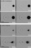
Images of shock wave propagation and secondary cavitation formation, obtained with multiple illumination technique, for different pump laser pulse energies: a) after breakdown and b) after collapse. Source position a3.

References

    1. Požar T., Petkovšek R. Cavitation induced by shock wave focusing in eye-like experimental configurations. Biomed Opt. Express. 2020;11:432–447. doi: 10.1364/BOE.11.000432. - DOI - PMC - PubMed
    1. Lauterborn W., Vogel A. In: Bubble Dynamics and Shock Waves. Delale C.F., editor. Springer; Berlin Heidelberg: 2013. Shock wave emission by laser generated bubbles; pp. 67–103. - DOI
    1. Petkovšek R., Možina J., Močnik G. Optodynamic characterization of the shock waves after laser-induced breakdown in water. Opt. Express. 2005;13:4107. doi: 10.1364/OPEX.13.004107. - DOI - PubMed
    1. Požar T., Agrež V., Petkovšek R. Laser-induced cavitation bubbles and shock waves in water near a concave surface. Ultrason. Sonochem. 2021;73:105456. doi: 10.1016/j.ultsonch.2020.105456. - DOI - PMC - PubMed
    1. Lee T., Cheong Y., Baac H.W., Guo L.J. Origin of Gouy phase shift identified by laser-generated focused ultrasound. ACS Photonics. 2020;7:3236–3245. doi: 10.1021/acsphotonics.0c01313. - DOI

LinkOut - more resources