Review
. 2022 Aug 30;12(37):24374-24389.
doi: 10.1039/d2ra05222a. eCollection 2022 Aug 22.

Insight into nanocrystal synthesis: from precursor decomposition to combustion

Affiliations
Review

Insight into nanocrystal synthesis: from precursor decomposition to combustion

Buzuayehu Abebe et al. RSC Adv. .

Abstract

Nanotechnology-based synthesis of nanoscale materials has appealed to the attention of scientists in the modern scientific community. In the bottom-up approach, atoms start to aggregate/agglomerate and form nuclei within the minimum and maximum supersaturation range. Once nuclei are generated above the critical-free energy/radius, the growth is initiated by obeying the LaMar model with a slight extra simple growth by diffusion advancement. The in situ real-time liquid phase analysis using STEM, AFM, and XAS techniques is used to control precursor decomposition to the nanocrystal formation process and should be a non-stoppable technique. Solution combustion synthesis (SCS) is a time-/energy-efficient self-sustained process that produces mass-/ion transport active porous materials. SCS also permits the synthesis of evenly distributed-doped and hybrid-nanomaterials, which are beneficial in tuning crucial properties of the materials. The growth and development of nanocrystals, dehydrating the sol in the presence of a surfactant or/and fuel results in combustion once it arrives at the ignition temperature. Besides, the kinetic and thermodynamics controlled architecture-directing agent-assisted SCS offers colloidal nanocrystal framework formation, which is currently highly applicable for energy devices. This short review provides insightful information that adds to the existing nanocrystal synthesis process and solution combustion synthesis and recommends future directions in the field.


Conflict of interest statement

There are no conflicts to declare.

Figures

Fig. 1
Fig. 1. The LaMer model of nucleation and growth: the diagram show the generation of atoms, nucleation, and subsequent growth of colloidal systems. Reproduced/Adapted from ref. with permission from The Royal Society of Chemistry.
Fig. 2
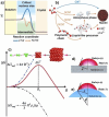
Fig. 2. Classical nucleation theory. (a) Energy landscapes for classical and non-classical nucleation. (b) Classical and non-classical nucleation pathways. (c) Nucleation barrier; Nuclei have to reach a critical size before they become thermodynamically stable. (d) Heterogeneous nucleation on a flat substrate; nucleation preferentially occurs on substrates due to the reduced nucleation barrier. (e) Heterogeneous nucleation on a curved substrate. Reproduced/Adapted from ref. with permission from The Royal Society of Chemistry.
Fig. 3
Fig. 3. Oriented attachment via nanobridge-induced contact. (a) Atomic resolution ADF-STEM time series show the OA process of two small Pt nanocrystals, indicating the approach of nanocrystals and pre-alignment by rotation, followed by nano bridge formation (marked by the black arrow in the inset at 85 s) and subsequent fusion of the nanocrystals. (b) Schematic illustration of the nano bridge-induced OA process. Images in the insets are shown in false colour. Reproduced/Adapted from ref. with permission from The Springer Nature.
Fig. 4
Fig. 4. Nanocrystal growth by monomer attachment and Ostwald ripening. (a) ADF-STEM time-series showed a particle growing by monomer attachment, where visible attachment of free Pt atoms (white arrows) forms new atomic layers on top of the old ones (red arrows). (b) ADF-STEM time-series showed a particle growing by Ostwald ripening, where single atoms and clusters migrate through a liquid from the smaller particle (top) to the larger particle (bottom). At the bottom is a schematic illustration of the Ostwald ripening process. The yellow arrows highlight the single atoms and clusters detached from the smaller particle. Images are shown in false colour. Reproduced/Adapted from ref. with permission from The Springer Nature.
Scheme 1
Scheme 1. Schematic diagrams show synthesizing homogeneous and phase-separated HEA-NPs by FMBP and FBP strategies, respectively. Reproduced/Adapted from ref. with permission from The Springer Nature.
Fig. 5
Fig. 5. (a) Formed EDL around a NP due to the Gouy–Chapman model which consists of the inner Stern layer and the outer diffuse layer (b) corresponding decrease in the counter- and co-ion concentrations with respect to the distance from the particle surface; (c) schematic of the EDL, van der Waals and total interaction potentials of two NPs; (d) and (e) influence of the ion concentration and the particle size on the TIP. Reproduced/Adapted from ref. with permission from The Royal Society of Chemistry.
Fig. 6
Fig. 6. Adsorption and cobridging of (a) PVP molecules in (b) a surface layer via Au-atoms on a gold particle. Reproduced/Adapted from ref. with permission from The American Chemical Society.
Fig. 7
Fig. 7. (a) Schematic illustration of the role of a capping agent in directing the growth of a single-crystal seed into nanocrystals with different shapes Reproduced/Adapted from ref. with permission from The American Chemical Society. (b) Overgrowth process of Ag nanocrystals, in which Ag atoms are continuously deposited onto the {100} facets of Ag nanocube to eventually result in an octahedron enclosed by {111} facets.
Fig. 8
Fig. 8. A proposed three-step pathway for gold nucleation in solution. (a) TEM images show the intermediate steps in nucleating gold nanocrystals from a supersaturated aqueous Au0 solution. From 3.0 to 9.2 s, the supersaturated Au0 solution spontaneously demixes into gold-poor and gold-rich liquid phases (lighter and darker regions, respectively) via spinodal decomposition. Amorphous gold nanoclusters emerge (11.3 s) from the gold-rich phases that crystallize (15.4 s). Insets show Fourier transforms of cropped square regions (orange) with the Au(111) fcc reciprocal lattice spacing circled in red. (b) Schematic of the proposed steps in nucleation (gold as orange spheres, with surrounding water as blue bent lines). Reproduced/Adapted from ref. with permission from The Springer Nature.
Fig. 9
Fig. 9. Scheme representation of the self-sustained combustion process: (a) infrared images for reaction front propagation (b) SEM images of quenched front in a nickel nitrate–glycine gel and (c) iron nitrate–glycine. Reproduced/Adapted from ref. with permission from The American Chemical Society.
Fig. 10
Fig. 10. Schematic diagram of the synthesis process of catalysts by solution combustion. Reproduced/Adapted from ref. with permission from The Royal Society of Chemistry.
Fig. 11
Fig. 11. Expected structure of Fe (Al)–urea–nitrate complex Reproduced/Adapted from ref. with permission from The American Chemical Society.
Fig. 12
Fig. 12. (a–c) TG–DSC–MA results are obtained for the dried gel prepared from the sol with a fuel-oxidant ratio of 1 : 1; (d) XRD patterns revealing the crystal structures of the combustion products of the dried gels for different fuel-oxidant ratios; (e) comparison of XRD patterns of CoCrCuNiAl high-entropy alloys synthesized by sol–gel auto combustion and mechanical alloying; (f) XRD patterns of the combustion product of the gels with a fuel–oxidant ratio of 0.8 : 1 and the schematic illustration of high-entropy alloys Reproduced/Adapted from ref. with permission from The Springer Nature.
Fig. 13
Fig. 13. A schematic representation of the mechanism for Ni formation during self-sustained reactions of nickel nitrate–glycine gels Reproduced/Adapted from ref. with permission from The American Chemical Society.
Fig. 14
Fig. 14. Schematic of the CSCS method for synthesizing crystalline mesoporous CeO2 with tailored porosity: (a) evaporation of water (b) combustion process (c) cooling (d) etching. Reproduced/Adapted from ref. with permission from The American Chemical Society.
None
Buzuayehu Abebe
None
Dereje Tsegaye
None
H. C. Ananda Murthy

Similar articles

Cited by

References

    1. Khort A. Hedberg J. Mei N. Romanovski V. Blomberg E. Odnevall I. Sci. Rep. 2021;11:7860. - PMC - PubMed
    1. LaMer V. K. Dinegar R. H. J. Am. Chem. Soc. 1950;72:4847–4854.
    1. Reiss H. J. Chem. Phys. 1951;19:482–487.
    1. Matijevic E. Chem. Mater. 1993;5:412–426.
    1. Li Q. Jun Y.-S. Commun. Chem. 2018;1:56.