Review
. 2020 Apr 16;2(5):1792-1810.
doi: 10.1039/d0na00219d. eCollection 2020 May 19.

Comprehensive understanding of the synthesis and formation mechanism of dendritic mesoporous silica nanospheres

Affiliations
Review

Comprehensive understanding of the synthesis and formation mechanism of dendritic mesoporous silica nanospheres

Pan Hao et al. Nanoscale Adv. .

Abstract

The interest in the design and controlled fabrication of dendritic mesoporous silica nanospheres (DMSNs) emanates from their widespread application in drug-delivery carriers, catalysis and nanodevices owing to their unique open three-dimensional dendritic superstructures with large pore channels and highly accessible internal surface areas. A variety of synthesis strategies have been reported, but there is no basic consensus on the elucidation of the pore structure and the underlying formation mechanism of DMSNs. Although all the DMSNs show a certain degree of similarity in structure, do they follow the same synthesis mechanism? What are the exact pore structures of DMSNs? How did the bimodal pore size distributions kinetically evolve in the self-assembly? Can the relative fractions of small mesopores and dendritic large pores be precisely adjusted? In this review, by carefully analysing the structures and deeply understanding the formation mechanism of each reported DMSN and coupling this with our research results on this topic, we conclude that all the DMSNs indeed have the same mesostructures and follow the same dynamic self-assembly mechanism using microemulsion droplets as super templates in the early reaction stage, even without the oil phase.


Conflict of interest statement

There are no conflicts to declare.

Figures

Fig. 1
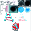
Fig. 1. Schematic illustration of dendritic mesoporous silica nanospheres (DMSNs) with the unique branching architecture, which is reminiscent of natural mineral dendrimers and artificial organic dendrimers.
Fig. 2
Fig. 2. SEM (a) and TEM (b) images and proposed formation mechanism (c) of mesoporous silica nanoparticles prepared by Okuyama and his coworkers with styrene. Reproduced with permission from ref. 59. Copyright 2009 Elsevier Ltd. And TEM (d) and SEM (e) images and proposed formation mechanism (f) of mesoporous silica nanoparticles prepared by Holmberg without styrene. Reproduced with permission from ref. 60. Copyright 2016 Elsevier Ltd.
Fig. 3
Fig. 3. (A) Schematic of the silica nanosphere (KCC-1) formation proposed by Basset. CPB: cetylpyridinium bromide, TEOS: tetraethyl orthosilicate. Reproduced with permission from ref. 62. Copyright 2010 Wiley-VCH. (B) SEM and (C) TEM images of KCC-1 with their illustrations drawn in (D) and (E), respectively. (F) Self-assembly of the silicate oligomer for the formation of bicontinuous morphology (the ABA silicate oligomer consists of two A blocks (blue) separated by a B block (red), where the A block consists of O–H groups in the terminal and the B block is a Si–O–Si chain of the oligomers. This pattern is similar to that of ABA triblock copolymer chains where A and B blocks are formed from different monomers. When the B blocks of polysiloxane have a range of chain lengths, a bicontinuous structure is formed). Reproduced with permission from ref. 66. Copyright 2016 American Chemical Society.
Fig. 4
Fig. 4. (a) Schematic (upper panel) and SEM/TEM images (lower panel) of silica nanoparticles synthesized with different volume ratios of cyclohexane to 15 mL of an aqueous solution of urea (0.3 g), CPB (0.5 g) and iso-propanol (0.46 mL), and (b) schematic illustration of the mesophase forming mechanism at the microemulsion interface. Reproduced with permission from ref. 67. Copyright 2012 American Chemical Society. The illustration (c) and SEM images (d–l) of silica-based nanoparticles synthesized from the different biphase regions of Winsor II (a–c),Winsor III (d–f) and Winsor I (g–i), respectively. Reproduced with permission from ref. 68. Copyright 2014 American Chemical Society.
Fig. 5
Fig. 5. (A) Synthesis process of the 3D-dendritic MSNSs and the mechanism of interfacial growth, (a) nucleation process of the 3D-dendritic MSNSs; (b) growth process of the first generation of the 3D-dendritic MSNSs; (c) changing the upper oil phase; (d) growth process of the second generation of the 3D-dendritic MSNSs; (e–h) the mechanism of one single mesopore-channel growth with swelling. TEM (B–D) and SEM (E–G) images of the extracted 3D-dendritic MSNSs with one (B and E), two (C and E), and three generations (D and G) prepared via the biphase stratification approach. All scale bars in the TEM and SEM images are 200 nm. Reproduced with permission from ref. 69. Copyright 2014 American Chemical Society.
Fig. 6
Fig. 6. A picture of a dahlia photographed by C. Xu in Tasmania (A). TEM images at low magnification (B) and high magnification (C), an ET slice (D) and the proposed formation mechanism (E) of MSN-CC. Reproduced with permission from ref. 71. Copyright 2015 Wiley-VCH.
Fig. 7
Fig. 7. (a) The chemical structure of organosilane F13 and the TEM image of mesoporous silica nanoparticles synthesized with a molar ratio of F13/TEOS of 1 : 10 (b) and 1 : 5 (c). Reproduced with permission from ref. 91. Copyright 2011 American Chemical Society. (d) A cross section of the conceptual model of a multifunctionalized SiO2 nanoparticle prepared by Paula, and the STEM micrographs of unfunctionalized (e) and phenyl-decorated SiO2 nanoparticles (f), scale bar = 25 nm. Reproduced with permission from ref. 92. Copyright 2012 The Royal Society of Chemistry.
Fig. 8
Fig. 8. (a) Schematic representation of the molecular organic–inorganic hybrid composition of thioether-bridged DMOSNs. (b) The proposed M/P-CA strategy to enlarge the micelle size of CTAC by incorporating the hydrophobic long organic chains of the as-hydrolyzed BTES into the hydrophobic part of the initially formed CTAC micelles. And corresponding TEM images (d and f) of DMOSNs at different magnifications (inset of (f): the pore shape of DMOSNs). Bright-field (c) and dark-field (e) STEM images of DMOSNs. N2 adsorption–desorption isotherm (g) and (inset of (g)) the corresponding pore size distribution of DMOSNs. Reproduced with permission from ref. 93. Copyright 2015 Wiley-VCH.
Fig. 9
Fig. 9. (a) Scale-up synthesis with tunable mesostructures via the mono-micelle templating self-assembly strategy, and SEM (b, d and f) and TEM (c, e and g) images of samples synthesized with different small organic amines (SOAs) of triethyleneamine (b and c), triethanolamine (d and e), and 2-amino-2-(hydroxymethyl) propane-1,3-diol (f and g). Reproduced with permission from ref. 95. Copyright 2013 American Chemical Society.
Fig. 10
Fig. 10. (a) Dual template synergistically controlled micelle self-aggregated model to understand the formation mechanism of dendritic MSNs; (b) pore networks of the typical dendritic MSNs observed by TEM. The red, green and brown circles indicate the small, intermediate and large pores using monomicelles, bimicelles and aggregated micelles as the templates or structure building units, respectively (inset 1, pore networks of classical amorphous silica sol particles; inset 2, the hexagonal pore array of MCM-41 or SBA-15); (c) pore size distribution (PSD) of typical dendritic MSNs synthesized by using the dual-templating strategy in the presence of the anionic sodium stearate (SS) surfactant calculated by the BJH method from both desorption branches. Reproduced with permission from ref. 122. Copyright 2017 The Royal Society of Chemistry.
Fig. 11
Fig. 11. (A1) A dahlia-like DMSN and (A2) a pomegranate-like MSN and (B) the kinetic micelle filling mechanism. The dahlia-like DMSNs (B1) are first assembled by an anion-assisted approach through lamellar building blocks. By gradually filling the large dendritic pores with composite micelles, we obtained a series of intermediate structures (B2) and small-pore MSNs with the dendritic pores completely filled (B3). Objects are not drawn to scale; TEM images (C–F) of MSNs at a fixed reaction temperature of 80 °C and a FC2/CTAB molar ratio of 1 at various reaction times of (C) 0.3, (D) 1, (E) 2, and (F) 5 h. Reproduced with permission from ref. 100. Copyright 2018 American Chemical Society.
Fig. 12
Fig. 12. Interfacial charge shielding (ICS) directs the synthesis of MSNs with varied mesostructures by precisely controlling the interactions between the cationic surfactant micelle (S+) and negative inorganic silicate species (I): route I, solo template method using a single CTA+ surfactant for the synthesis of MSNs and MCM-41 silica at a high pH value; route II, the cationic–anionic dual surfactant template approach for dendritic MSNs with 3.0 nm mesopores using the anionic sodium dodecyl sulphate (SDS) surfactant as the co-template; route III: the cationic–nonionic dual surfactant template strategy for dendritic MSNs with large mesopores (>5.0 nm) using nonionic NP-7 or Tween 80 as the co-template. Reproduced with permission from ref. 128. Copyright 2019 The Royal Society of Chemistry.
Fig. 13
Fig. 13. Bright-field TEM (a) and high-resolution HAADF-STEM (b) images of 1% Ag2O/1% Au-DMSNs. Corresponding STEM EDX mapping images of Au/Ag2O: (c) Au (yellow), (d) Ag (blue) and (e) Au/Ag merged (green), respectively. The inset in (a) shows that DMSNs have small, ill-ordered spherical pores (∼3 nm) nested in the dendritic channel networks. Reproduced with permission from ref. 151. Copyright 2019 The Royal Society of Chemistry.
Fig. 14
Fig. 14. Illustration of the surface spatial confinement strategy (red spheres: Ni NPs). (a) Ni NPs between the layers are prevented from migrating; (b) Ni NPs between the mesopores are prevented from migrating; (c) reactants can be transferred freely between the mesopores. Reproduced with permission from ref. 160. Copyright 2013 American Chemical Society.
Fig. 15
Fig. 15. Ligand assembly in the MSNs free of metals and their tunable luminescence properties. Scanning electron microscopy (SEM) (a) and TEM (b) images of the as-synthesized fluorescent mesoporous silica nanoparticles. The inset shows the assembly of amino- and carbonyl-groups in the confined nanopores (the scale bar in a and b is 200 and 100 nm, respectively). (c) Excitation and emission spectra of aminopropyl-functionalized MSNs. (d) Absorption and emission spectra of propylsuccinic-functionalized MSNs.
Fig. 16
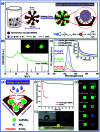
Fig. 16. Spatially and chemically confined ultra-small CsPbBr3 perovskite QDs in dendritic mesoporous silica nanospheres with enhanced stability for the fabrication of LEDs. Reproduced with permission from ref. 165. Copyright 2020 Elsevier Ltd.
None
Bo Peng
None
Tai-Qun Yang
None
Kun Zhang

Similar articles

Cited by

References

    1. Beck J. S. Vartuli J. C. Roth W. J. Leonowicz M. E. Kresge C. T. Schmitt K. D. Chu C. T.-W. Olson D. H. Sheppard E. W. McCullen S. B. Higgins J. B. Schlenker J. L. J. Am. Chem. Soc. 1992;114:10834–10843. doi: 10.1021/ja00053a020. - DOI
    1. Zhao D. Feng J. Huo Q. Melosh N. Fredrickson G. H. Chmelka B. F. Stucky G. D. Science. 1998;279:548–552. doi: 10.1126/science.279.5350.548. - DOI - PubMed
    1. Wan Y. Zhao D. Chem. Rev. 2006;107:2822–2860.
    1. Taguchi A. Schüth F. Microporous Mesoporous Mater. 2005;77:1–45. doi: 10.1016/j.micromeso.2004.06.030. - DOI
    1. Trewyn B. G. Slowing I. I. Giri S. Chen H. T. Lin V. S.-Y. Acc. Chem. Res. 2007;40:846–853. doi: 10.1021/ar600032u. - DOI - PubMed