Review
. 2021 Jan 21;3(5):1230-1260.
doi: 10.1039/d0na01005g. eCollection 2021 Mar 9.

Structure and luminescence of DNA-templated silver clusters

Affiliations
Review

Structure and luminescence of DNA-templated silver clusters

Anna Gonzàlez-Rosell et al. Nanoscale Adv. .

Abstract

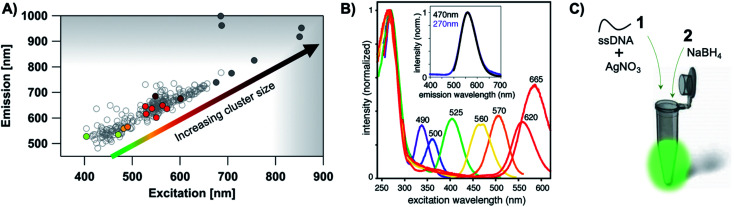
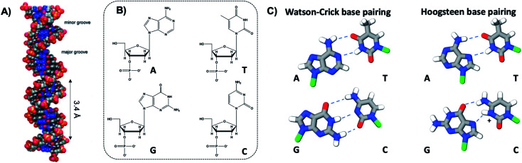
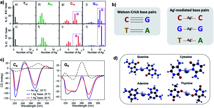
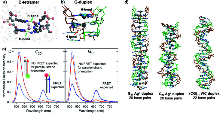
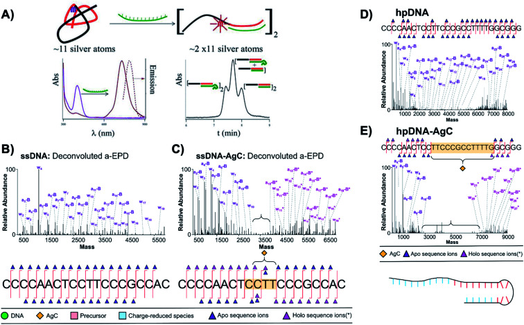
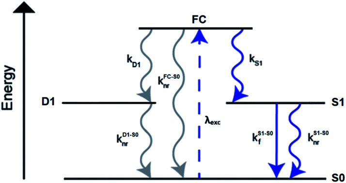
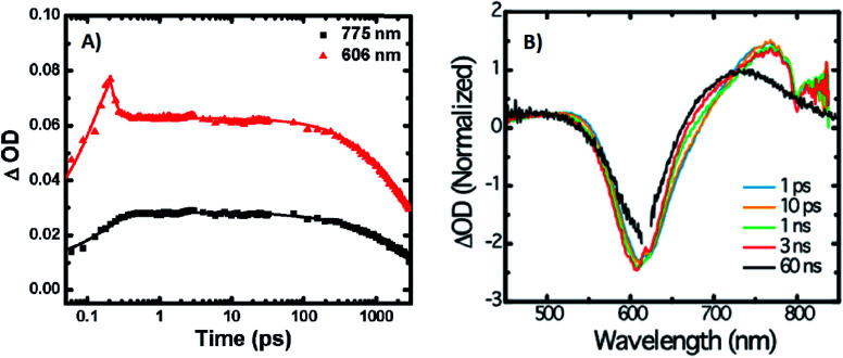
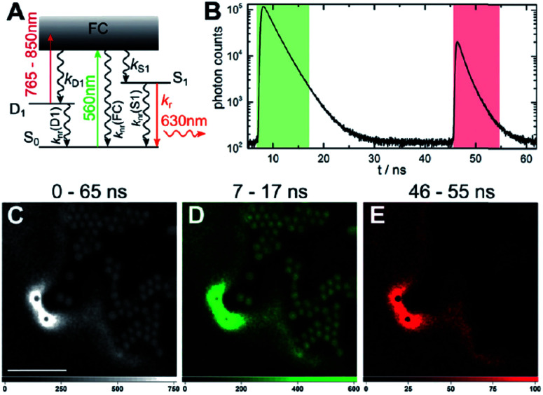
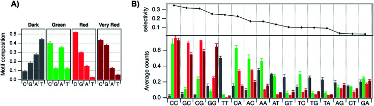
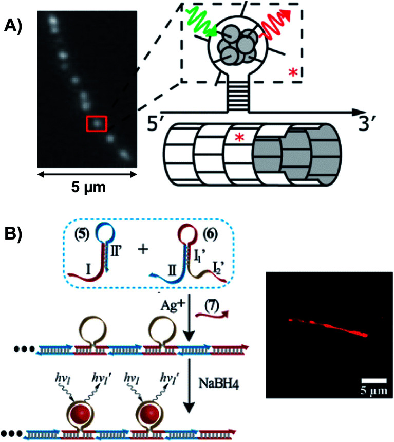
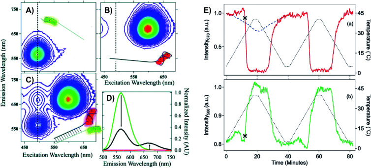
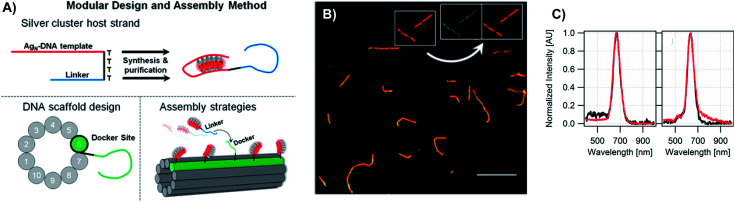
DNA serves as a versatile template for few-atom silver clusters and their organized self-assembly. These clusters possess unique structural and photophysical properties that are programmed into the DNA template sequence, resulting in a rich palette of fluorophores which hold promise as chemical and biomolecular sensors, biolabels, and nanophotonic elements. Here, we review recent advances in the fundamental understanding of DNA-templated silver clusters (Ag N -DNAs), including the role played by the silver-mediated DNA complexes which are synthetic precursors to Ag N -DNAs, structure-property relations of Ag N -DNAs, and the excited state dynamics leading to fluorescence in these clusters. We also summarize the current understanding of how DNA sequence selects the properties of Ag N -DNAs and how sequence can be harnessed for informed design and for ordered multi-cluster assembly. To catalyze future research, we end with a discussion of several opportunities and challenges, both fundamental and applied, for the Ag N -DNA research community. A comprehensive fundamental understanding of this class of metal cluster fluorophores can provide the basis for rational design and for advancement of their applications in fluorescence-based sensing, biosciences, nanophotonics, and catalysis.


Conflict of interest statement

There are no conflicts to declare.

Figures

Fig. 1
Fig. 1. (A) The fluorescence colors of AgN-DNAs, which are selected by DNA sequence, span a large spectral range from visible to NIR wavelengths and are correlated with cluster size. (B) AgN-DNA excitation spectra exhibit a dominant peak in the visible to NIR spectral range as well as a UV excitation band corresponding exactly to the DNA template strand. Fluorescence spectra excited via the DNA bases (inset, purple) have the same lineshapes as spectra excited at the cluster's unique visible to NIR transition. Adapted from O'Neill, et al., (ref. 21) with permission from the American Chemical Society. Copyright 2011. (C) AgN-DNAs are chemically synthesized in aqueous solution by mixing ssDNA with a silver salt, followed by reduction with sodium borohydride.
Fig. 2
Fig. 2. (A) Illustration of the double helix structure of natural Watson–Crick-paired B form DNA. Adapted from Bandy, et al. (ref. 82) with permission from the Royal Society of Chemistry. (B) Chemical structure of the natural nucleotides and (C) the H-bonded configurations of the nucleobases. Green regions represent the bonding positions of the nucleobases to the backbone.
Fig. 3
Fig. 3. (A) Percentages of integrated counts (IC) for each product detected by ESI-MS for mixtures of Ag and 11-base homobase strands, at two different stoichiometries. Pink boxes and “D” represent Ag+-paired duplexes. (B) Summary of WC H-bonded base pairs and observed Ag+-mediated base pairs for duplexes of homobase strands. (C) Circular dichroism (CD) spectra for C6–Ag+–C6 and G6–Ag+–G6 show the significant thermal stabilities of these homobase-Ag+ duplexes. (D) Calculations of ground state geometries for Ag+-mediated homobase pairs finds planar geometries for G and C and nonplanar geometries for A and T, with binding energies of the trend G  >  C  >  A  >  T. (A, C and D) Adapted from Swasey, et al., (ref. 54) with permission from Springer Nature. Copyright 2015.
Fig. 4
Fig. 4. (A, B) DFT calculations predict the existence of novel inter-strand H-bonds in (A) C2–Ag+–C2 tetramers and (B) Ag+-paired G duplexes of varying lengths. These bonds add additional stability to Ag+-paired DNA duplexes. (A) Adapted from Espinosa Leal, et al., (ref. 101) with permission from the American Chemical Society. Copyright 2015. (C) Emission spectra of Ag+-mediated C20 and G15 duplexes labeled with donor (green dot) and acceptor (red dot) dyes at 5′ end and 3′ end, respectively (orange curve) or with both dyes at 3′ ends (blue), compared to emission of the donor-bearing strand alone (blue dotted curve). Excitation is at 450 nm, which directly excites the donor only. Significant quenching of donor emission with concomitant acceptor emission (high FRET efficiency) clearly demonstrates that Ag+-mediated pairing of homo-duplexes arranges strands in a parallel orientation. (D) DFT-optimized structures of Ag+–DNA duplexes of G20 and C20 compared to WC duplexes of a mixed base (GC)11 show that Ag+ mediates formation of highly rigid duplexes of G homo-base strands and less rigid C homo-base duplexes. Ag+–DNA nanowires have parallel duplex strand orientation, as compared to canonical antiparallel strand orientation of WC duplexes. (B–D) Adapted from Swasey, et al., (ref. 108) with permission from the American Chemical Society. Copyright 2018.
Fig. 5
Fig. 5. (A) MS-determined distributions of the numbers of Ag+ attached to DNA oligomers (sequences indicated on each graph) determined by relative integrated intensity of individual mass peaks relative to all silver-bearing duplexes. Single-base mutations in G-rich oligomers enable attachment of many more Ag+. Adapted with permission from Swasey, et al. (ref. 55) with permission from the Institute of Physics. (B) Crystal structure of an Ag+-paired DNA duplex with antiparallel orientation. End-to-end assembly of these duplexes forms uninterrupted nanowires. Protruding adenines foster assembly of multiple wires into 3D lattices. Silver atoms are shown in gray and potassium atoms in purple. Image created from PDB ID 5IX7 with NGL Viewer. (C) Structure of a dimer of 5′-GCACGCGC-3′ (orange, green) paired by two Ag+ (grey). The third Ag+ (bottom right of structure) supports supramolecular assembly of the structure during crystallization. Image created from PDB ID 5XJZ with PyMOL.
Fig. 6
Fig. 6. Tutorial schematic of tandem HPLC-MS with in-line UV/Vis and fluorescence spectroscopy, developed by Schultz and Gwinn. (A) In this illustration, the initial sample (yellow tube) is a mixture of products including multiple dark Ag-DNA complexes, one green-fluorescent AgN-DNA species, and one red-fluorescent AgN-DNA species. The as-synthesized AgN-DNA solution is injected into an HPLC outfitted with a core–shell C18 column for reverse-phase, ion-pair (IP) HPLC. Products are separated due to slight variations in column affinity with a water–methanol gradient and a triethyl ammonium acetate (TEAA) IP agent. By monitoring both absorbance at ∼260 nm, which correlates to the absorbance of DNA, and fluorescence emission (e.g. UV-excited fluorescence), correlation of absorbance and fluorescence chromatogram peaks indicate elution of a fluorescent AgN-DNA species. We note that the chromatogram schematics are simplified for illustration; real chromatograms are more complex. Products of interest can either be sized by in-line negative-ion mode ESI-MS or collected for subsequent ESI-MS. A mass spectrum for a previously studied 30-atom NIR-emissive product is shown in the bottom right. Both monomeric and dimeric (labeled “D”) products are visible, with spacing of the isotopic peaks indicating the charge state of each product (labeled as superscript of “D”) for dimeric products. (B) Experimental mass spectrum of the Ag30-DNA product at the 7− charge state dimeric product (labeled D−7 in (A)) is shown in black, with the calculated mass distribution (green bars) for a product with 2 DNA strands, N0 = 12 Ag0, and N+ = 18 Ag+. Inset: compares the experimental spectrum with the calculated distribution for a product with no charged silvers (2 DNA strands and 30 Ag0), illustrating how the shift between the experimental and calculated isotopic finger distribution can be used to accurately determine the numbers of Ag0 and Ag+ in an AgN-DNA product. Mass spectra are adapted from Swasey, et al., (ref. 23) with permission from the Royal Society of Chemistry.
Fig. 7
Fig. 7. (A) Peak absorbance energies for purified AgN-DNAs characterized by MS as a function of the number of effective free electrons in the cluster (red). Experimental data are better described by simulations of silver nanorods with 1-atom cross-sections (green line) than for thicker nanorods with 6-atom cross-sections (gray line) or spherical clusters (blue band). Adapted from Schultz, et al., (ref. 24) with permission from John Wiley and Sons. Copyright 2013. (B) Neutral Ag atom numbers, N0, as determined by HR-MS for HPLC-purifiable AgN-DNAs, including brightly fluorescent AgN-DNAs (colored dots with RGB color matching fluorescence wavelength (NIR = gray)) and AgN-DNAs without measurable fluorescence (black). (C) Histogram of N0 values show abundances of clusters with even N0 as compared to magic numbers 2 and 8 predicted by the spherical “superatom” model. (B and C) Adapted from Copp, et al., (ref. 57) with permission from the American Chemical Society. Copyright 2014.
Fig. 8
Fig. 8. (A) Mass spectrum of 20-base DNA-templated AgN. The peaks labeled −10 to −5 correspond to the ions of the AgN-DNA, while the peaks labeled −8 DNA to −6 DNA are ascribed to the ions of the bare DNA strand. The inset shows the zero-charge spectrum that identifies the native DNA at 5878 amu and the DNA with 10 Ag at 6951 amu. (B) CD spectra of AgN-DNAs at different temperatures. (C) Ag K-edge EXAFS trace of the solution state AgN-DNAs. The experimental data (black) was fitted (red) with three individual scattering paths (magenta, purple and blue) displayed separately. (D) Suggested AgN-DNA structure after combining all information from MS and EXAFS measurements. Adapted from Petty, et al., (ref. 130) with permission from the American Chemical Society. Copyright 2016.
Fig. 9
Fig. 9. Ag 3d peak doublet for (A) Ag+–DNA complexes, (B) AgNO3 salt, (C) HPLC-purified fluorescent AgN-DNAs (which combine both neutral and cationic Ag) and (D) metallic Ag nanoparticles. Adapted from Volkov, et al., (ref. 158) with permission from the American Chemical Society. Copyright 2017.
Fig. 10
Fig. 10. IR spectra of (A) bare DNA (black) and red-emitting AgN-DNA (red) and (B) ss-DNA homopolymers of all four DNA nucleobases with (red) or without (black) Ag(i). Adapted from Schultz, et al., (ref. 159) with permission from The Royal Society of Chemistry.
Fig. 11
Fig. 11. Asymmetric unit of the Ag8-DNA reported by Huard, et al., with the 8-atom cluster (as defined in the authors' report) indicated by the gray spheres and additional silvers associated with crystal packing indicated by blue spheres. (B) Illustration of silver atoms only, for various crystal sections. (C and D) Structure of the Ag8-DNA in (C) Sections 0 to 2 and (D) Sections 3 to 5 as defined in (B). One silver atom (orange) is stabilized by an adenine from a neighboring DNA strand. Details on the structure can be found at the PDB database using accession code 6NIZ.
Fig. 12
Fig. 12. (A) Subunit structure of the Ag16-DNA (5′-CACCTAGCG-3′). Silvers with occupancy of 1 are gray, while lower occupancy silvers (∼0.3) are magenta. (B) Cluster structure with DNA removed, with sections numbered. (C) Sections 0 and 1, (D) Section 1 and a part of Section 2, and (E) Section 2 of the Ag16-DNA subunit. (F) Section 3, and (G) Sections 4 and 5 of the Ag16-DNA. Red dashed lines indicate Ag–Ag interactions, and black lines represent coordination bonds. Details on the structure of the NIR emissive Ag16-DNA can be found at the PDB database using accession code 6M2P. Adapted from Cerretani, et al., (ref. 25) with permission from The Royal Society of Chemistry.
Fig. 13
Fig. 13. (A) Schematic of a sensor formed by a ∼11 Ag atom cluster with violet absorption, which converts into a NIR emissive cluster of twice the size upon hybridization with a target strand (green). Bottom right: Size exclusion chromatogram shows three separate peaks when a 10-thymine tail is appended to the target strand, indicating that the NIR AgN-DNA forms by complexation of two DNA sensors. Adapted from Petty, et al., (ref. 38) with permission from the American Chemical Society. Copyright 2013. (B–D) Deconvoluted a-EPD spectra and sequence coverage maps for a ssDNA template (B) without and (C) with an Ag10 and for a “hairpin” DNA template (D) without and (E) with an Ag10. Comparison of spectra with and without the Ag10 shows suppression of fragmentation for certain subregions of the DNA templates, which are correlated to regions where the DNA templates interact with their Ag10 clusters. Adapted from Blevins, et al., (ref. 121) with permission from the American Chemical Society. Copyright 2019.
Fig. 14
Fig. 14. General phenomenological model for AgN-DNAs. S0 and S1 represent the ground and emissive states, respectively, FC indicates the initially populated Franck-Condon state, and D1 is the dark state. The dashed blue line stands for the absorption process, wavy lines represent non-radiative pathways, and the straight line defines the emissive decay. Adapted from Cerretani, et al., (ref. 185) with permission from the Royal Society of Chemistry.
Fig. 15
Fig. 15. (A) Femtosecond transient absorption kinetic traces for 680 nm emissive (“Ag680”) AgN-DNAs. The wavelengths shown for this emitter reflect the transient absorption (black) and the ground-state depletion (red). The depletion appears at negative ΔOD, but is plotted in its absolute value. It has been corrected for the spectral overlap by subtracting the contribution from the transient absorption, which is based on the kinetics at 775 nm calibrated to the expected value based on the peak curve fittings. The data was collected by exciting with a 100 fs Ti-sapphire laser at 1 kHz, then probing with a white light continuum generated from the same laser. The excitation wavelength was tuned to the peak of the ground state absorption. (B) Normalized femtosecond and nanosecond transient absorption spectra for Ag680. The sample was excited by 100 fs pulsed excitation, except for the long delay time curve, which was generated from excitation by a 7 ns pulsed laser. The dip in the spectrum around 800 nm is an instrumental artifact. Adapted from Patel, et al., (ref. 193) with permission from the American Chemical Society. Copyright 2009.
Fig. 16
Fig. 16. OADF microscopy. (A) Energy diagram for OADF of a red emissive AgN-DNA. Vertical colored arrows indicate absorption of a photon from primary (560 nm) and secondary (765–850 nm) excitation lasers and fluorescence emission at 630 nm, respectively. (B) Primary fluorescence decay curve (first decay after excitation with 560 nm at 7 ns) and OADF decay (second decay after illumination with 765–850 nm at 46 ns) for red AgN-DNA embedded in PVA. (C–E) Fluorescence images of a heterogeneous sample of fluorescently-labeled polystyrene microspheres, which are auto-fluorescent to simulate undesired background, and red-emitting AgN-DNAs within PVA film (the signal of interest). Images were constructed using (C) all detected photons (0–65 ns), (D) primary fluorescence (7–17 ns) and (E) OADF signal (46–55 ns). Scale bar corresponds to 10 μm. The time gates used to construct images (D) and (E) are shown in (B) with the same colors. Images acquired with 3.7 kW cm−2 primary excitation power. Adapted from Krause, et al., (ref. 30) with permission from the Royal Society of Chemistry.
Fig. 17
Fig. 17. (A) TRES, (B) average decay time as a function of emission wavelength, and (C) DAS of red emissive AgN-DNAs at 25 °C, excited at 561 nm. The gray line in (C) indicates the zero line. In order to construct TRES and DAS, the intensity decays were acquired from 575 nm to 725 nm, in steps of 5 nm. The three decay time values were globally linked in the fit. Adapted from Cerretani, et al., (ref. 185) with permission from the Royal Society of Chemistry.
Fig. 18
Fig. 18. Anisotropy decays of a NIR AgN-DNA in 10 mM NH4OAc aqueous solution at 5 °C, 25 °C, and 40 °C. Data was fitted assuming a single rotational correlation time. Adapted from Bogh, et al., (ref. 176) with permission from the Institute of Physics.
Fig. 19
Fig. 19. Schematic of the workflow for supervised learning applied to prediction of DNA template sequences for brightly fluorescent AgN-DNAs. Adapted from Copp, et al., (ref. 215) with permission from John Wiley and Sons. Copyright 2014.
Fig. 20
Fig. 20. (A) Distribution of peak fluorescence emission wavelength for AgN-DNAs stabilized by ∼2000 different 10-base DNA templates, with arrows and colors indicating the color classes defined in the text. (B) Numbers of DNA sequences in color classes from (A), corresponding to samples with bright spectral peaks in only one class (gray). Other sequences exhibited secondary bright peaks in a different color class (checkered blue) but were omitted from the training data in order to best learn the features of DNA sequences suitable for only one size of fluorescent AgN-DNA. (C) Cross-validation scores for trained one-versus-one SVMs. The color bar indicates score value, which is also indicated by text on each pixel. (A–C) Adapted from Copp, et al., (ref. 175) with permission from the American Chemical Society. Copyright 2018. (D) Distributions of observed fluorescence peaks for 10-base AgN-DNA training data (black) and AgN-DNAs designed by ML (colored bars) for Red 600–660 nm fluorescence (target color band indicated by orange brackets). Designed DNA template strand lengths vary: 8 bases (purple), 10 bases (blue), 12 bases (green), and 16 bases (red). Adapted from Copp, et al., (ref. 111) with permission from the American Chemical Society. Copyright 2020.
Fig. 21
Fig. 21. Average numbers of (A) single bases and (B) two-base patterns in motifs identified by feature selection to be correlated to AgN-DNA color (bar color indicates sequence class: gray = Dark, green = Green, red = Red, dark red = Very Red). In (B), two-base patterns are ordered along the horizonal axis by selectivity, defined to be the standard deviation of the heights of the four bars for each base pattern. Adapted from Copp, et al., (ref. 175) with permission from the American Chemical Society. Copyright 2018.
Fig. 22
Fig. 22. (A) Schematic and fluorescence micrograph of an AgN-DNA-labeled DNA nanotube, with clusters templated by hairpin protrusions on select DNA tiles (red asterisk). Adapted from O'Neill, et al., (ref. 100), with permission from the American Chemical Society. Copyright 2012. (B) Schematic of hybridization chain reaction (HCR) forming wire scaffolds for AgN-DNA synthesis, and fluorescence micrograph of synthesized AgN-DNA wire. Adapted from Orbach, et al., (ref. 118) with permission from the American Chemical Society. Copyright 2013.
Fig. 23
Fig. 23. (A) Excitation–emission maps (EEMs) for an HPLC-purified green-emissive donor AgN-DNA, (B) red-emissive acceptor AgN-DNA, (C) and the WC-paired clamp. The EEM of the duplex is not simply an addition of (A) and (B) because FRET causes emission of the acceptor via excitation of the donor, evidenced by two peaks along the black dashed line in (C). (D) Emission spectra for 490 nm excitation of donor (green), acceptor (red), and WC pair (black). (E) FRET is cycled (intensity: green and red lines) by thermal melting (temperature: dashed black line) and reformation of the FRET pair. Adapted from Schultz, et al., (ref. 222) with permission from the American Chemical Society. Copyright 2013.
Fig. 24
Fig. 24. (A) Scheme of design method for modular AgN-DNA template strand with linker, DNA nanotube scaffold with complementary docker strand, and assembly. (B) Spinning disc confocal microscopy of nanotubes labeled with 670 nm emissive AgN-DNAs (red color) and FAM (organic dye, green) embedded in a polyvinyl alcohol film shows that AgN-DNAs bind to the DNA nanotubes. Scale bar: 10 μm. (C) UV-excited fluorescence spectra of Ag15 (left) and Ag14 (right) free in solution (black) and after attachment to nanotubes with an excess of docker sites to ensure complete binding. Adapted from Copp, et al., (ref. 200) with permission from the American Chemical Society. Copyright 2015.
Fig. 25
Fig. 25. (A) Schematic of well plate reader for NIR rapid screening of candidate fluorophores, using an InGaAs PIN-type femtowatt photodetector. Adapted from Swasey, et al., (ref. 226) with permission from AIP Publishing. (B) Colormaps of well plates containing AgN-DNAs scanned using the modified plate reader, with box colors indicating peak emission wavelength and box size indicating relative fluorescence intensity. (C) Absorbance and emission spectra for three NIR-AgN-DNAs identified in (B) and purified by HPLC, including the longest-wavelength emitting AgN-DNA identified to date (bottom panel). (D) Mass spectrum of the AgN-DNA associated with the top panel of (C), as measured using ESI-MS. (B–D) Adapted from Swasey, et al., (ref. 23) with permission from the Royal Society of Chemistry.
None
Anna Gonzàlez-Rosell
None
Cecilia Cerretani
None
Peter Mastracco
None
Tom Vosch
None
Stacy M. Copp

References

    1. Schmid G. Chem. Rev. 1992;92:1709–1727. doi: 10.1021/cr00016a002. - DOI
    1. de Heer W. Rev. Mod. Phys. 1993;65:611–676. doi: 10.1103/RevModPhys.65.611. - DOI
    1. Schmid G. Maihack V. Lantermann F. Peschel S. J. Chem. Soc. Dalt. Trans. 1996:589. doi: 10.1039/DT9960000589. - DOI
    1. Jin R. Zeng C. Zhou M. Chen Y. Chem. Rev. 2016;116:10346–10413. doi: 10.1021/acs.chemrev.5b00703. - DOI - PubMed
    1. Zheng J. Dickson R. M. J. Am. Chem. Soc. 2002;124:13982–13983. doi: 10.1021/ja028282l. - DOI - PubMed