Review
. 2020 Jul 28;2(10):4341-4349.
doi: 10.1039/d0na00519c. eCollection 2020 Oct 13.

Rare-earth-free magnetically hard ferrous materials

Affiliations
Review

Rare-earth-free magnetically hard ferrous materials

Zefan Shao et al. Nanoscale Adv. .

Abstract

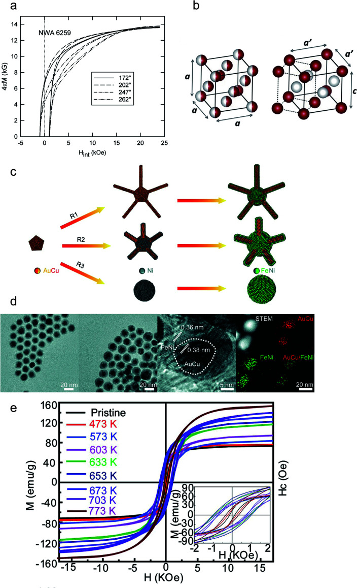
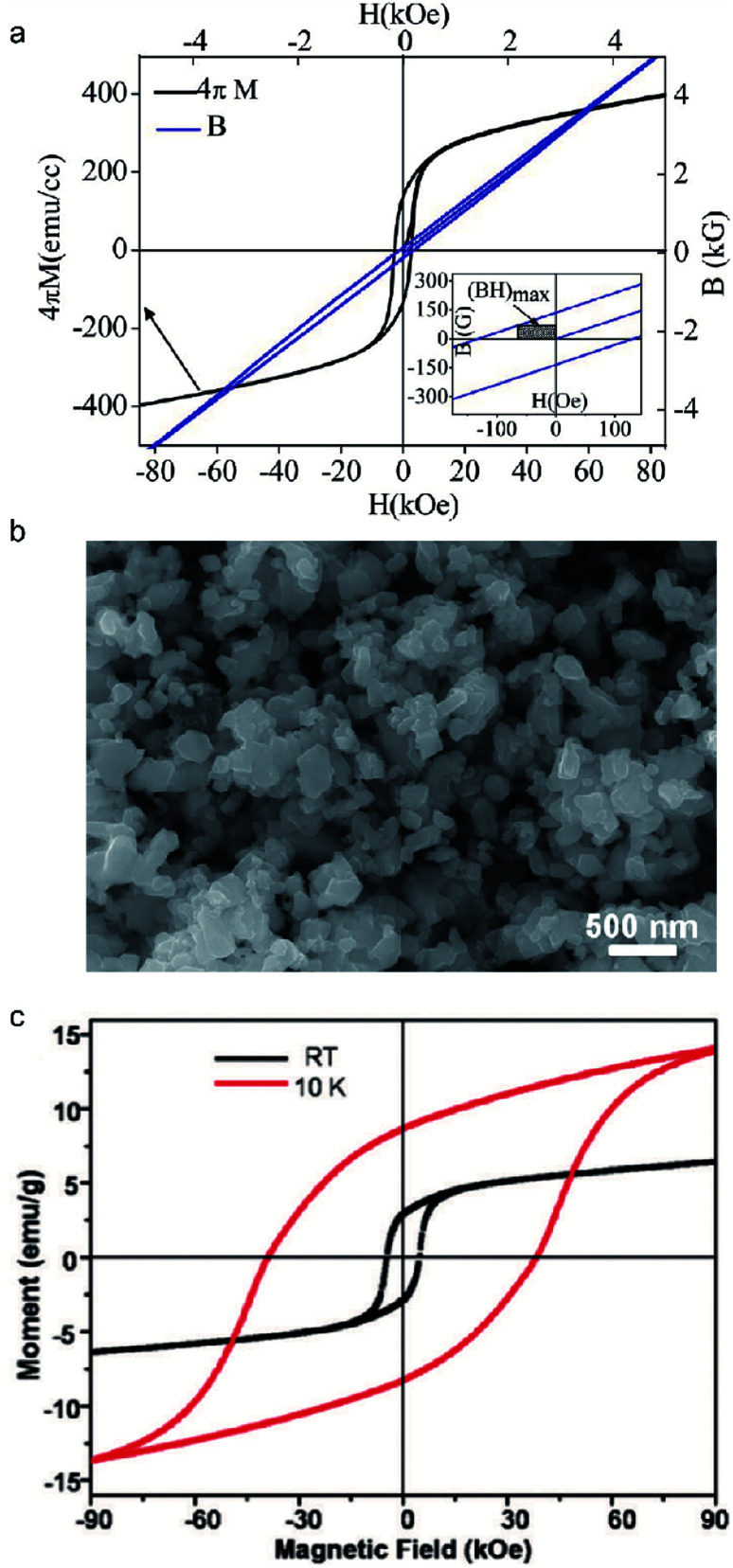
Permanent magnets, especially rare-earth based magnets, are widely used in energy-critical technologies in many modern applications, involving energy conversion and information technologies. However, the environmental impact and strategic supplies of rare-earth elements hamper the long-term development of permanent magnets. Hence, there is a surge of interest to expand the search for rare-earth-free magnets with a large energy product (BH)max. Among these rare-earth-free magnets, iron-based permanent magnets emerge as some of the most promising candidates due to their abundance and magnetic performance. In this review, we present a summary of iron-based permanent magnets from materials synthesis to their magnetic properties.


Conflict of interest statement

There are no conflicts to declare.

Figures

Fig. 1
Fig. 1. (a) Evolution of market distribution of REE demand; (b) magnetic properties of various hard magnetic materials. Reproduced from ref. 16,17 and 18 with the permission of Elsevier, American Chemical Society and Springer Nature.
Fig. 2
Fig. 2. (a) The calculated total energy (ΔE) and magnetocrystalline anisotropy energy (EMCA) of FeCo along the (001) direction; (b) a schematic illustration of the crystal structure of FeCo/FePt(001); (c) magnetic hysteresis loops for an FeCo/FePt thin film; (d) schematic figure of the AuCu/FeCo (core/shell) nanocrystal synthesis; (e) the TEM image of AuCu/FeCo (core/shell) nanoparticles; (f) the M–H loops of L10 AuCu/FeCo particles. The inset shows the annealing temperature-dependent coercivity of L10 AuCu/FeCo. Reproduced from ref. 42, 45, 46 and 48 with the permission of AIP Publishing, Elsevier and American Chemical Society.
Fig. 3
Fig. 3. (a) Annealing temperature dependence of coercivity for FePd nanoparticles dispersed on NaCl (001) substrates covered with a-Al2O3 thin films; (b) magnetic hysteresis loops and TEM image of monodisperse FePd; (c) schematic illustration of self-aggregation of FePd–Fe; (d) high-resolution (HRTEM) image of the L10-FePd-Fe nanoparticles; (e) magnetic hysteresis loops of FePd nanoparticles which are controlled by the exchange-coupling method at different temperatures; (f) eutectic salt melt synthesis and crystallization of FePd powder prepared by a eutectic reaction; (g) the TEM image of FePd nanoparticles prepared by a eutectic reaction; (h) magnetic hysteresis loops of FePd with different precursors prepared by a eutectic reaction. Reproduced from ref. 54, 55, 57, 58 and 59 with the permission of IOP Publishing, Elsevier, American Chemical Society and Royal Society of Chemistry.
Fig. 4
Fig. 4. (a) Magnetic hysteresis loops of FePt prepared by a chemical route at 10 K; (b) schematic illustration of chemically ordered fct-FePt; (c) the TEM image of monodisperse FePt; (d) TEM bright field images of tunable FePt particles; (e) schematic illustration of the FePt nanoparticle formation mechanism; (f) schematic illustration of the synthesis of L10-FePt; (g) the TEM image of L10-FePt nanoparticles; (h) magnetic hysteresis loops of L10-FePt nanoparticles; (i) the calculated energy product of FePt–Co magnets. Reproduced from ref. 62, 64, 65 and 66 with the permission of IOP Publishing, American Chemical Society and Royal Society of Chemistry.
Fig. 5
Fig. 5. (a) The formation sequence of Fe16N2; (b) magnetic hysteresis loops of Fe16N2 prepared by ball milling and shock compaction; (c) saturation magnetization of Fe films against pressure which were separately deposited in a nitrogen atmosphere and vacuum; (d) magnetic hysteresis loops of Fe16N2 at room temperature; (e) the calculated energy product for Fe16N2 at room temperature; (f) the TEM diffraction pattern of Fe16N2 with 5 × 10¹⁷ions per cm2 fluence. Reproduced from ref. 68, 69, 71 and 20 with the permission of Elsevier, AIP Publishing, John Wiley and Sons and Springer Nature.
Fig. 6
Fig. 6. (a) Magnetic hysteresis loops of ε-Fe2O3 prepared by Jin et al.; (b) procedure to prepare SiO2-coated ε-Fe2O3 nanorods; (c) TEM image of ε-Fe2O3; (d) crystal structure of the ε-phase; (e) schematic illustration of synthesis of ε-Fe2O3 on a silica template; (f) magnetic hysteresis loops of oriented ε-Fe2O3 at 300 K; (g) magnetic hysteresis loops of powdered ε-Fe2O3 embedded in a silica matrix at 300 K; (h) magnetic hysteresis loops of ε-Fe2O3 oriented at different temperatures. Reproduced from ref. 75, 76, 77, 78 and 79 with the permission of John Wiley and Sons, Springer Nature, and AIP Publishing.
Fig. 7
Fig. 7. (a) Magnetic hysteresis of NWA 6259 tetrataenite; (b) representations of the cubic (A1) and tetragonal (L10) unit cells of FeNi; (c) schematic images of the synthesis procedure of AuCu/FeNi (core/shell) nanocrystals; (d) TEM images of AuCu/FeNi (core/shell) nanostructures at different shell thicknesses. (e) The magnetic hysteresis loops of AuCu/FeNi (core/shell) nanocrystals with the stoichiometry of Fe46Ni54 at different annealing temperatures, and the inset images show the corresponding magnified hysteresis loops. Reproduced from ref. 84, 85 and 87 with the permission of AIP Publishing, Elsevier, and American Chemical Society.
Fig. 8
Fig. 8. (a) Magnetic characteristics of Fe3Se4 nanocrystals at 300 K. (Inset) Calculation of the maximum energy product of Fe3Se4; (b) typical SEM images of the as-synthesized Fe3Se4 nanoplatelets; (c) magnetic loops of faceted Fe3Se4 nanoparticles measured with a field of 90 kOe at 10 K and room temperature. Reproduced from ref. 88, 91 and 92 with the permission of American Chemical Society.
None
Zefan Shao
None
Shenqiang Ren

References

    1. Galioto S. J. Reddy P. B. El-Refaie A. M. Alexander J. P. IEEE Trans. Ind. Appl. 2014;51:2148–2160.
    1. Ghidini M. Pellicelli R. Prieto J. Moya X. Soussi J. Briscoe J. Dunn S. Mathur N. Nat. Commun. 2013;4:1–7. - PubMed
    1. Morimoto S. Tong Y. Takeda Y. Hirasa T. IEEE Trans. Ind. Electron. 1994;41:511–517. doi: 10.1109/41.315269. - DOI
    1. Haavisto M. Paju M. IEEE Trans. Magn. 2009;45:5277–5280.
    1. Chen L., Wang J., Lazari P. and Chen X., Optimizations of a permanent magnet machine targeting different driving cycles for electric vehicles, 2013 International Electric Machines & Drives, IEEE, 2013, pp. 855–862