

Micro 3D printing of a functional MEMS accelerometer
- PMID: 36133693
- PMCID: PMC9482918
- DOI: 10.1038/s41378-022-00440-9
Micro 3D printing of a functional MEMS accelerometer
Abstract
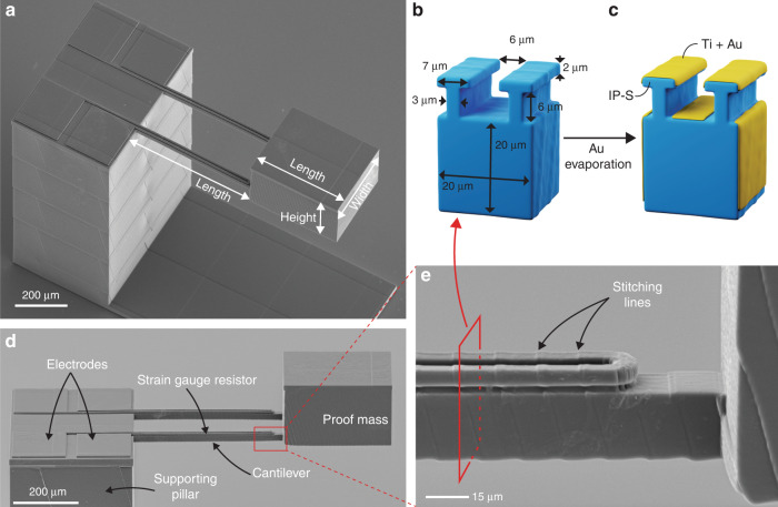
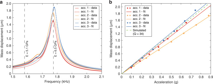
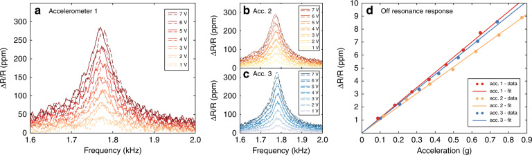
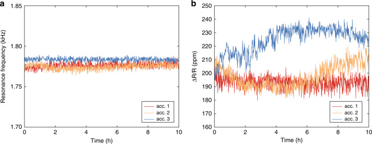
Microelectromechanical system (MEMS) devices, such as accelerometers, are widely used across industries, including the automotive, consumer electronics, and medical industries. MEMS are efficiently produced at very high volumes using large-scale semiconductor manufacturing techniques. However, these techniques are not viable for the cost-efficient manufacturing of specialized MEMS devices at low- and medium-scale volumes. Thus, applications that require custom-designed MEMS devices for markets with low- and medium-scale volumes of below 5000-10,000 components per year are extremely difficult to address efficiently. The 3D printing of MEMS devices could enable the efficient realization and production of MEMS devices at these low- and medium-scale volumes. However, current micro-3D printing technologies have limited capabilities for printing functional MEMS. Herein, we demonstrate a functional 3D-printed MEMS accelerometer using 3D printing by two-photon polymerization in combination with the deposition of a strain gauge transducer by metal evaporation. We characterized the responsivity, resonance frequency, and stability over time of the MEMS accelerometer. Our results demonstrate that the 3D printing of functional MEMS is a viable approach that could enable the efficient realization of a variety of custom-designed MEMS devices, addressing new application areas that are difficult or impossible to address using conventional MEMS manufacturing.
Keywords: Electrical and electronic engineering; Nanoscience and technology.
© The Author(s) 2022.
Conflict of interest statement
Conflict of interestThe authors declare no competing interests.
Figures
Similar articles
-
3D-Printed MEMS in Italy.Micromachines (Basel). 2024 May 22;15(6):678. doi: 10.3390/mi15060678. Micromachines (Basel). 2024. PMID: 38930648 Free PMC article. Review.
-
Printing MEMS: Application of Inkjet Techniques to the Manufacturing of Inertial Accelerometers.Micromachines (Basel). 2023 Nov 10;14(11):2082. doi: 10.3390/mi14112082. Micromachines (Basel). 2023. PMID: 38004939 Free PMC article.
-
Additive manufacturing of three-dimensional (3D) microfluidic-based microelectromechanical systems (MEMS) for acoustofluidic applications.Lab Chip. 2018 Jul 10;18(14):2087-2098. doi: 10.1039/c8lc00427g. Lab Chip. 2018. PMID: 29897358 Free PMC article.
-
3D Printed MEMS Technology-Recent Developments and Applications.Micromachines (Basel). 2020 Apr 20;11(4):434. doi: 10.3390/mi11040434. Micromachines (Basel). 2020. PMID: 32326136 Free PMC article.
-
3D printed electronics with nanomaterials.Nanoscale. 2023 Mar 23;15(12):5623-5648. doi: 10.1039/d2nr06771d. Nanoscale. 2023. PMID: 36880539 Review.
Cited by
-
Additive Manufactured Strain Sensor Using Stereolithography Method with Photopolymer Material.Polymers (Basel). 2023 Feb 16;15(4):991. doi: 10.3390/polym15040991. Polymers (Basel). 2023. PMID: 36850274 Free PMC article.
-
Femtosecond Laser Direct Writing of Gecko-Inspired Switchable Adhesion Interfaces on a Flexible Substrate.Micromachines (Basel). 2023 Sep 6;14(9):1742. doi: 10.3390/mi14091742. Micromachines (Basel). 2023. PMID: 37763905 Free PMC article.
-
Direct laser writing-enabled 3D printing strategies for microfluidic applications.Lab Chip. 2024 Apr 30;24(9):2371-2396. doi: 10.1039/d3lc00743j. Lab Chip. 2024. PMID: 38576361 Free PMC article. Review.
-
3D Printing of Glass Micro-Optics with Subwavelength Features on Optical Fiber Tips.ACS Nano. 2024 Apr 23;18(16):10788-10797. doi: 10.1021/acsnano.3c11030. Epub 2024 Mar 29. ACS Nano. 2024. PMID: 38551815 Free PMC article.
-
A polymeric piezoelectric MEMS accelerometer with high sensitivity, low noise density, and an innovative manufacturing approach.Microsyst Nanoeng. 2023 Nov 29;9:151. doi: 10.1038/s41378-023-00628-7. eCollection 2023. Microsyst Nanoeng. 2023. PMID: 38033989 Free PMC article.
References
-
- Lawes RA. Manufacturing costs for microsystems/MEMS using high aspect ratio microfabrication techniques. Microsyst. Technol. 2007;13:85–95. doi: 10.1007/s00542-006-0252-6. - DOI
-
- Rayna T, Striukova L. From rapid prototyping to home fabrication: How 3D printing is changing business model innovation. Technol. Forecast. Soc. Change. 2016;102:214–224. doi: 10.1016/j.techfore.2015.07.023. - DOI
-
- Shahrubudin, N., Lee, T. C. & Ramlan, R. An overview on 3D printing technology: technological, materials, and applications. Procedia Manuf.35, 1286–1296 (2019).
-
- Yusuf, S. M., Cutler, S. & Gao, N. Review: The impact of metal additive manufacturing on the aerospace industry. Metals9, 1286 (2019).
LinkOut - more resources
Full Text Sources