Review
. 2022 Aug 24;9(9):1274.
doi: 10.3390/children9091274.

Double-Inlet Left Ventricle

Affiliations
Review

Double-Inlet Left Ventricle

P Syamasundar Rao. Children (Basel). .

Abstract

Double-inlet left ventricle (DILV) is most frequent among univentricular atrioventricular connections. In DILV, there is a single functioning ventricle, most commonly with left ventricular structure. This chamber receives both atrioventricular valves and is connected to an outlet chamber with morphologic features of the right ventricle. The great vessels are often transposed, and pulmonary stenosis is seen in two-thirds of patients. The anatomy and pathophysiology can be defined by echo-Doppler studies with a rare need for other imaging studies. The management is mostly related to the nature of associated heart defects and the degree of pathophysiological abnormality. When the infants present initially, treatment to address the hemodynamic issues is undertaken. Subsequently, these babies need staged total cavo-pulmonary connection, i.e., the Fontan procedure which is undertaken in three stages; these stages are described in this review. The existence of inter-stage mortality and post-Fontan complications is recognized and was reviewed. The paper concludes that DILV can be successfully diagnosed with echo-Doppler studies and this heart anomaly can be effectively treated with the currently prevailing medical, catheter interventional, and surgical treatment practices.

Keywords: Blalock–Taussig anastomosis; Fontan surgery; banding of the pulmonary artery; bidirectional Glenn operation; double-inlet left ventricle; inter-stage mortality; single ventricle.


Conflict of interest statement

The author declares no conflict of interest.

Figures

Figure 1
Figure 1
Selected video frames from two different patients. (A) shows the ventricular septum between the ventricles in a normal child while (B) demonstrates the absence of the ventricular septum. The figures show top-to-bottom reversal; this is because these figures were prepared prior to the American Society of Echocardiography recommendation of the current way in which we display the images. Left atrium (LA), left ventricle (LV), right atrium (RA), right ventricle (RV), and single ventricle (SV) are labeled.
Figure 2
Figure 2
The 2D echo images from apical four-chamber projections of two children, one with two ventricles (A) and another with a single ventricle (SV) (B). These figures were prepared after the American Society of Echocardiography recommendations of the current way in which we display the images. Left atrium (LA), left ventricle (LV), right atrium (RA), and right ventricle (RV) are marked. Reproduced from Reference [4].
Figure 3
Figure 3
The 2D echo images from apical four-chamber projections of a child who was diagnosed to have double inlet left ventricle (DILV). (A) shows closed and (B) shows open atrioventricular valves as indicated by arrows. No evidence for a ventricular septum is seen. The right ventricle is not imaged in this projection (see Figure 4). Left atrium (LA) and right atrium (RA) are labeled. Reproduced from Reference [3].
Figure 4
Figure 4
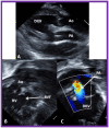
The 2D echo/color Doppler images from the parasternal long axis (A) and modified apical (B,C) projections of the case illustrated in Figure 3, indicating transposed great arteries (A). Note the anterior location of the aorta (Ao) and posterior location of the pulmonary artery (PA) (A). The connection of the right ventricular (RV) chamber with the double-inlet left ventricle (DILV) via a bulbo-ventricular foramen (BVF) is seen in (B). This RV provides an origin to the aorta (Ao) as shown in (B). The pulmonary artery (PA) arises from the main ventricle, DILV, as seen in (C). Turbulent flow in the PA is seen (C) and is suggestive of obstruction. Continuous wave Doppler (not illustrated) demonstrated increased Doppler velocity indicative of severe pulmonary narrowing. Reproduced from Reference [3].
Figure 5
Figure 5
Selected video images secured from the suprasternal notch view of the arch of the aorta (Ao) in two-dimensional (A) and color Doppler (B) pictures demonstrating coarctation of the aorta (CoA) and hypoplastic transverse aortic arch (TAA). Descending aorta (DAo) is labeled. Reproduced from Reference [6].
Figure 6
Figure 6
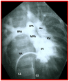
Selected cine frame in the postero-anterior projection of a single ventricular (SV) cine-angiogram demonstrating simultaneous opacification of the main (MPA), left (LPA), and right (RPA) pulmonary arteries from the SV and the aorta (Ao) from the right ventricle (RV). Note that the Ao is positioned to the left of the MPA, indicating l-transposition of the great vessels. C1. Catheter in the inferior vena cava (not marked) which was advanced into the right atrium (RA) and then into the SV; C2. Catheter in the descending aorta (not marked).
Figure 7
Figure 7
(A) Hand drawing (drawn by Dr. Taussig herself) illustrating the concept of the Blalock–Taussig shunt [25] showing the anastomosis of the subclavian arteries (SCAs) to the left (LPA) or right (RPA) pulmonary arteries, respectively. (B) Selected frame from a cine-angiogram of the Gore-Tex graft (GG) showing modified Blalock–Taussig (BT) shunts [18]. This image demonstrates widely patent BT shunt and excellent visualization of the pulmonary artery (PA). AAo, ascending aorta; LSA, left subclavian artery.
Figure 8
Figure 8
Selected video images secured with the transducer positioned in the suprasternal notch illustrating the proximal part of the shunt (PS) with color Doppler (A). In another transducer angulation (B), the Doppler flow from the distal portion of the shunt (DS) into both the right (RPA) and left (LPA) pulmonary arteries is imaged. Reproduced from Reference [26].
Figure 9
Figure 9
(A) Pictorial depiction of pulmonary artery banding (PB) for babies with severely augmented blood flow into the lungs and heart failure. (B) Cine image from a pulmonary artery cine-angiogram in conventional lateral projection illustrating the narrowed segment of the pulmonary artery (PB) indicated by an arrow in a baby who underwent PB. The catheter (C), left pulmonary artery (LPA), nasogastric tube (NG), pigtail catheter (PG), and right pulmonary artery (RPA) are labeled.
Figure 10
Figure 10
Selected echo-Doppler images illustrating the pulmonary artery band (PAB). Note, narrow PAB diameter by two-dimensional echo in (A) and by color Doppler imaging in (B). Continuous wave Doppler reveals a significant gradient (81 mmHg) across the PAB (C). Reproduced from Reference [26].
Figure 11
Figure 11
Echo images secured with the transducer positioned in the suprasternal notch illustrating the bidirectional Glenn shunt. Note that the superior vena cava (SVC) is draining into the right (RPA) and left (LPA) pulmonary arteries shown by color Doppler (A). Low Doppler flow velocities through the bidirectional Glenn shunt (B) indicate that the shunt is not obstructed. Reproduced from Reference [26].
Figure 12
Figure 12
Cine-angiographic images illustrating bidirectional Glenn procedure in two separate children (a,b). The unimpeded flow of blood from the superior vena cava (SVC) to the right (RPA) and left (LPA) pulmonary arteries is demonstrated. Sternal wires related to previous surgical procedures are shown and are not labeled. Reproduced from Reference [12].
Figure 13
Figure 13
Selected cine-angiographic images demonstrating the bilateral bidirectional Glenn procedure. (a) This is an angiogram with contrast injection into the right superior vena cava (SVC) illustrating rapid visualization of the right pulmonary artery (RPA). The unopacified blood from a persistent left superior vena cava (PLSVC) is shown with an arrow in “(a)”. (b). This is an angiogram from the PLSVC demonstrating rapid visualization of the left pulmonary artery (LPA). The unopacified blood from the right SVC is shown with an arrow in “(b)”. These figures demonstrate flow of the contrast material from both the SVCs into the LPA and RPA, respectively, without obstruction. Reproduced from Reference [12].
Figure 14
Figure 14
Echo images illustrating anastomosis of the inferior vena cava (IVC) with the conduit (C) by 2D (A) and color flow (B) imaging. Note widely patent IVC–C junction both by 2D (A) and by laminar flow with color Doppler (B). Reproduced from Reference [26].
Figure 15
Figure 15
Echo images illustrating widely open conduit (COND) by 2D (A) and color flow imaging (B). Note laminar flow in B which suggests a lack of obstruction in the COND. Reproduced from Reference [26].
Figure 16
Figure 16
Echo images from an apical four chamber projection by 2D (A) and color flow (B) imaging demonstrating cross-sectional images of the conduit (C) in (A,B) and a fenestration (Fen) in (B). Note that the flow across the Fen is turbulent (B). Reproduced from Reference [26].
Figure 17
Figure 17
Cine-angiographic images in postero-anterior (a) and lateral (b) views, illustrating Stage IIIA of the Fontan operation rerouting the blood flow from the inferior vena cava (IVC) into the right (RPA) and left (LPA) pulmonary arteries through a non-valved Gore-Tex conduit (Cond). The flow of the contrast material via the fenestration (Fen) is indicated by the arrows in both a and b. HV, hepatic veins; PG, pigtail catheter. Modified from Reference [12].
Figure 18
Figure 18
Cine-angiographic images in antero-posterior projection, illustrating Stage IIIA Fontan operation transmitting blood flow from the inferior vena cava (IVC) into the pulmonary arteries through a non-valve Gore-Tex conduit (Cond). The fenestration (Fen) is indicated by an arrow in (a). The Fen was occluded with an Amplatzer device (D), again marked by an arrow in (b) (Stage IIIB). The hepatic veins (HV), left pulmonary artery (LPA), and right pulmonary artery (RPA) are labeled. Reproduced from Reference [12].
Figure 19
Figure 19
Echo images from apical four chamber projection illustrating the location of the Amplatzer device (D), indicated by arrows in (A,B). Note that there is no residual shunt demonstrated as shown in B. Conduit (C) is labeled. Reproduced from Reference [26].

References

    1. Rao P.S. Diagnosis and management of cyanotic congenital heart disease: Part II. Indian J. Pediatr. 2009;76:297–308. doi: 10.1007/s12098-009-0030-4. - DOI - PubMed
    1. Rao P.S. Other cyanotic heart defects in the neonate. In: Rao P.S., Vidyasagar D., editors. Perinatal Cardiology: A Multidisciplinary Approach. Cardiotext Publishing; Minneapolis, MN, USA: 2015. Chapter 37.
    1. Rao P.S. Other cyanotic heart defects in the neonate. In: Rao P.S., Vidyasagar D., editors. A Multidisciplinary Approach to Perinatal Cardiology. Volume 2. Cambridge Scholars Publishing; New Castle upon Tyne, UK: 2021. pp. 474–509.
    1. Rao P.S. Cardiac malpositions including heterotaxy syndromes. In: Rao P.S., Vidyasagar D., editors. A Multidisciplinary Approach to Perinatal Cardiology. Volume 2. Cambridge Scholars Publishing; New Castle upon Tyne, UK: 2021. pp. 432–466.
    1. Rao P. Subaortic obstruction after pulmonary artery banding in patients with tricuspid atresia and double-inlet left ventricle and ventriculoarterial discordance. J. Am. Coll. Cardiol. 1991;18:1585–1586. doi: 10.1016/0735-1097(91)90695-6. - DOI - PubMed

LinkOut - more resources