Review
. 2022 Sep 13;22(18):6931.
doi: 10.3390/s22186931.

Case-Study-Based Overview of Methods and Technical Solutions of Analog and Digital Transmission in Measurement and Control Ship Systems

Affiliations
Review

Case-Study-Based Overview of Methods and Technical Solutions of Analog and Digital Transmission in Measurement and Control Ship Systems

Mostafa Abotaleb et al. Sensors (Basel). .

Abstract

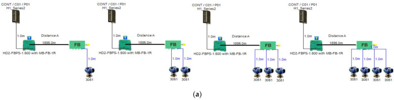
The purpose of this article is to provide an overview of possible solutions to improve the performance of measurement and control processes in maritime engineering applications. This improvement can be basically provided by adopting techniques to enhance the reliability of measurement/control systems based on the 4-20 mA analogue standard. This aspect will be discussed through a Simscape Simulink model illustrating methods of noise and ground loops elimination for pressure measurement of a 4-20 mA current loop in the tank level measurement system on a bulk carrier commercial ship. Alternatively, improved measurement and control processes can be rendered by utilizing smart transmitters based on wired hybrid analogue-digital (Highway Addressable Remote Transducer (HART)), wired digital (Foundation Fieldbus (FF)) or wireless (wireless HART) communication protocols. A brief theoretical description of these protocols will be presented in this article. As an example of using smart transmitters, a simulation-based case study will analyze the possible options to implement non-intrinsically safe as well as intrinsically safe FF models for the tank level measurement system on a bulk carrier commercial ship. Conclusions obtained through analysis of the simulation results will characterize the behavior of FF segments in safe as well as explosive hazardous areas, highlighting the characteristics of field barriers and segment protectors used in conjunction with the HPTC (High-Power Trunk Concept) intrinsically safe model.

Keywords: DART; FISCO; FNICO; Foundation Fieldbus; HPTC; field barriers; instrumentation amplifier; segment protectors; signal isolation; wireless HART.


Conflict of interest statement

The authors declare no conflict of interest. The funders had no role in the design of the study; the collection, the analysis and the interpretation of data; in the writing of manuscript or in the decision to publish the results.

Figures

Figure 1
Figure 1
Connection diagram between 4–20 mA pressure transmitters and I/O modules in control system.
Figure 2
Figure 2
Foundation Fieldbus OSI (open systems interconnection) model.
Figure 3
Figure 3
4–20 mA analogue pressure transmitter as a part of automation system.
Figure 4
Figure 4
Simulink Simscape model used to simulate 4–20 mA pressure measurement current loop as a part of automation system.
Figure 5
Figure 5
Illustration of 5 VDC voltage signal corresponding to 20 mA analogue current (1 bar of detected pressure). Upper figure illustrates voltage signal highly distorted by common mode noise at difference amplifier input. Middle figure illustrates the output voltage signal of instrumentation amplifier slightly distorted by coupled noise, while the lower figure illustrates output voltage after low-pass filtering.
Figure 6
Figure 6
Test segments (a,b) dedicated to deriving the relation between main FF trunk cable length and current consumed by field barriers. (a) Test segments using Rosemount 3051 Pressure Transmitters; (b) Test segments using Rosemount 5400 Radar Transmitters.
Figure 6
Figure 6
Test segments (a,b) dedicated to deriving the relation between main FF trunk cable length and current consumed by field barriers. (a) Test segments using Rosemount 3051 Pressure Transmitters; (b) Test segments using Rosemount 5400 Radar Transmitters.
Figure 7
Figure 7
Layout of field device connection blocks for FF models. Connections units used differ according to the model (megablocks, megablocks with SC protection, field barriers or segment protectors). DB and TS refer to double bottom and top side tanks, respectively. S and P refer to starboard and port sides of the ship, respectively. Letters a and b on each layout refer to segments included in each sub-model as indicated in Table 1. (a) Non-intrinsically safe and HPTC model. (b) Intrinsically safe entity model. (c) Intrinsically safe FISCO IIB model. (d) Intrinsically safe FISCO IIC model. (e) Intrinsically safe FISCO IIB SC model. (f) Intrinsically safe FNICO IIB model. (g) Intrinsically safe FNICO IIB SC model. (h) Intrinsically safe FNICO IIC model. (i) Intrinsically safe FNICO IIC SC model. (j) Intrinsically safe DART model.
Figure 7
Figure 7
Layout of field device connection blocks for FF models. Connections units used differ according to the model (megablocks, megablocks with SC protection, field barriers or segment protectors). DB and TS refer to double bottom and top side tanks, respectively. S and P refer to starboard and port sides of the ship, respectively. Letters a and b on each layout refer to segments included in each sub-model as indicated in Table 1. (a) Non-intrinsically safe and HPTC model. (b) Intrinsically safe entity model. (c) Intrinsically safe FISCO IIB model. (d) Intrinsically safe FISCO IIC model. (e) Intrinsically safe FISCO IIB SC model. (f) Intrinsically safe FNICO IIB model. (g) Intrinsically safe FNICO IIB SC model. (h) Intrinsically safe FNICO IIC model. (i) Intrinsically safe FNICO IIC SC model. (j) Intrinsically safe DART model.
Figure 8
Figure 8
Total current consumption and maximum allowable spur lengths of all sub-models.
Figure 9
Figure 9
Current and voltage drop on the cables included in sub-models dedicated to double bottom tanks. Blue, brown, yellow, violet and green colors refer to segments from 1 to 5, respectively.
Figure 9
Figure 9
Current and voltage drop on the cables included in sub-models dedicated to double bottom tanks. Blue, brown, yellow, violet and green colors refer to segments from 1 to 5, respectively.
Figure 10
Figure 10
Illustration of voltage at farthest field devices, total segments’ lengths and percentage of them to the maximum allowable length of 1900 m and total number of segments for double bottom tanks’ sub-models.
Figure 11
Figure 11
Current and voltage drop on the cables included in sub-models dedicated to top side tanks. Blue, brown, yellow and violet colors refer to segments from 1 to 4, respectively.
Figure 12
Figure 12
Illustration of voltage at farthest field devices, total segments’ lengths and percentage of them to the maximum allowable length of 1900 m and total number of segments for top side tanks’ sub-models.
Figure 13
Figure 13
Illustration of current consumed by field barrier with respect to FF H1 trunk cable length when for four models in which one, two, three or four 3051 transmitters were connected to the field barriers in the models in Figure 6a.
Figure 14
Figure 14
Illustration of current consumed by field barrier with respect to FF H1 trunk cable length when for four models in which one, two, three or four 5400 transmitters were connected to the field barriers in the models in Figure 6b. (Last plot for both 3051 and 5400 transmitters.)

References

    1. Dudojc B., Mindykowski J. New Approach to Analysis of Selected Measurement and Monitoring Systems Solutions in Ship Technology. Sensors. 2019;19:1775. doi: 10.3390/s19081775. - DOI - PMC - PubMed
    1. Abotaleb M., Mindykowski J., Dudojc B., Masnicki R. Digital Communication Links Cooperating with the Analog 4–20 mA Standard for Marine Applications. Bull. Polytech. Inst. Iași. Electr. Eng. Power Eng. Electron. Sect. 2021;67:21–44. doi: 10.2478/bipie-2021-0002. - DOI
    1. Berge J., Margo M.C., Pinceti P. Configuring Intelligent Field Devices. In: Liptak B.G., Venczel K., editors. Instrumentation and Automation Engineers’ Handbook. 5th ed. International Society of Automation (ISA); Durham, NC, USA: 2017. pp. 35–55. Volume 1: Measurement and Safety.
    1. Hidalgo R.O. Master’s Thesis. University of Stavanger; Stavanger, Norway: 2011. Sensor Diagnostic HART Overlay 4–20 mA; pp. 11–37.
    1. Park J., Mackay S., Wright E. Practical Data Communications for Instrumentation and Control. 1st ed. Newnes; Oxford, UK: 2003. pp. 238–249.