. 2022 Sep 23;12(1):15901.
doi: 10.1038/s41598-022-20247-y.

Limb, joint and pelvic kinematic control in the quail coping with steps upwards and downwards

Affiliations

Limb, joint and pelvic kinematic control in the quail coping with steps upwards and downwards

Emanuel Andrada et al. Sci Rep. .

Abstract

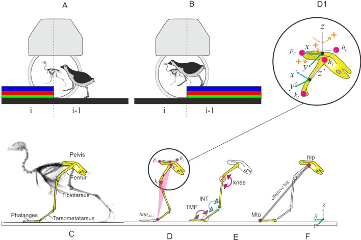
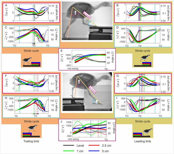
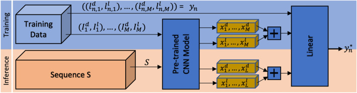
Small cursorial birds display remarkable walking skills and can negotiate complex and unstructured terrains with ease. The neuromechanical control strategies necessary to adapt to these challenging terrains are still not well understood. Here, we analyzed the 2D- and 3D pelvic and leg kinematic strategies employed by the common quail to negotiate visible steps (upwards and downwards) of about 10%, and 50% of their leg length. We used biplanar fluoroscopy to accurately describe joint positions in three dimensions and performed semi-automatic landmark localization using deep learning. Quails negotiated the vertical obstacles without major problems and rapidly regained steady-state locomotion. When coping with step upwards, the quail mostly adapted the trailing limb to permit the leading leg to step on the elevated substrate similarly as it did during level locomotion. When negotiated steps downwards, both legs showed significant adaptations. For those small and moderate step heights that did not induce aerial running, the quail kept the kinematic pattern of the distal joints largely unchanged during uneven locomotion, and most changes occurred in proximal joints. The hip regulated leg length, while the distal joints maintained the spring-damped limb patterns. However, to negotiate the largest visible steps, more dramatic kinematic alterations were observed. There all joints contributed to leg lengthening/shortening in the trailing leg, and both the trailing and leading legs stepped more vertically and less abducted. In addition, locomotion speed was decreased. We hypothesize a shift from a dynamic walking program to more goal-directed motions that might be focused on maximizing safety.


Conflict of interest statement

The authors declare no competing interests.

Figures

Figure 1
Figure 1
Experimental setup and 2D/3D global and joint limbs kinematics. The quail negotiated visible step-up (A) and step-down (B) steps of 1 cm (green), 2.5 cm (red), and 5 cm (blue) height. Body and hindlimb kinematics were captured using biplanar fluoroscopy. (C) Analyzed body segments. (D) 3D kinematics of the pelvis relative to the global coordinate system, and rotation of the whole leg related to the pelvis. The last estimates the three-dimensional rotations occurring at the hip joint. The whole leg is a plane formed by the hip (e.g., hl), the knee (e.g., kl) and the distal marker of the tarsometatarsus (tmtdist. l). Coordinate systems for the pelvis and the leg can be seen in D1, see methods for further explanations, (E) joint kinematics (INT intertarsal joint, TMP tarsometatarsal–phalangeal joint), (F) effective leg is the distance between tip of the middle toe (Mto) and the hip.
Figure 2
Figure 2
Effective leg kinematics during level and step locomotion. Level vs step-up (above): (A,B) effective leg length (l), effective leg axial velocity (l˙). (C,D) effective leg angle (α), effective leg angle velocity (α˙). (E) aperture angle between effective legs (ϕ) and aperture angle velocity (ϕ˙). Level vs drop (below): (F,G) effective leg length (l), effective leg axial velocity (l˙). (H,I) effective leg angle (α), effective leg angle velocity (α˙). (J) aperture angle between effective legs (ϕ) and aperture angle velocity (ϕ˙). Left: trailing leg stepping before the step up/downwards (stride i-1), right: leading leg stepping after the step up/downwards (stride i). Level (black) and step locomotion (1 cm: green, 2.5 cm: red, 5 cm: blue) in the quail. Solid lines: length/angle, dotted lines length/angle velocities. Curves display mean values. Black, blue, red, green dashed lines indicate toe-off (TO), while solid lines touch down (TD). Cyan solid lines indicate 15% and 85% of the stride. Due to the constrained field of view in the X-ray fluoroscope, hip data was often missing at the beginning and at the end of the stride cycles and average values less reliable (showed diffuse).
Figure 3
Figure 3
Joint angles. Level vs step-up (above): (A,B) knee; (C,D) intertarsal (INT); and (E,F) tarsometatarsal-phalangeal (TMP). Level vs drop (below): (G,H) knee; (I,J) INT; and (K,L) TMP. Left: trailing leg stepping before the step up/downwards (stride i-1), right: leading leg stepping after the step up/downwards (stride i). Curves display mean values of joint angles during level (black) and step locomotion (1 cm: green, 2.5 cm: red, 5 cm: blue) in the quail. Black, blue, red, green dashed lines indicate toe-off (TO), while solid lines touch down (TD). Cyan solid lines indicate 15% and 85% of the stride. Due to the constrained field of view in the X-ray fluoroscope, hip data was often missing at the beginning and at the end of the stride cycles and average values might be less reliable (showed diffuse).
Figure 4
Figure 4
Whole leg three-dimensional rotations in the quail. Motions were measured relative to the pelvis. Level (black) and step locomotion (1 cm: green, 2.5 cm: red, 5 cm: blue). Accepting that the knee, the intertarsal and the tarsometatarsal–phalangeal joints work mainly as revolute joints, the plane describing the whole-leg displays the three-dimensional hip control. Level vs step-up (above): (A,B) hip flexion extension (βh), negative values indicate flexion. (C,D) Hip mediolateral rotation (αh). Positive values indicate that the distal point of the whole leg moves laterally with respect to the hip; and (E,F) hip ad-abduction (γh). Level vs drop (below): (G,H) hip flexion extension; (I,J) mediolateral rotation; and (E,F) hip Ad-abduction. Curves display mean values. Left: trailing leg stepping before the step up/downwards (stride i-1), right: leading leg stepping after the step up/downwards (stride i). Black, blue, red, green dashed lines indicate toe-off (TO), while solid lines touch down (TD). Cyan solid lines indicate 15% and 85% of the stride. Due to the constrained field of view in the X-ray fluoroscope, hip data was often missing at the beginning and at the end of the stride cycles and average values might be less reliable (showed diffuse).
Figure 5
Figure 5
Pelvic three-dimensional rotations during level (black) and step locomotion in the quail. Curves display mean values. Left: step-up locomotion, right: step-down locomotion. For better understanding, we transformed the data to ensure that the trailing limb is always the left leg and the leading leg the right one (see methods). (A,D) pelvic pitch (βp), negative values indicate retroversion (trunk is more vertical oriented). (B,E) pelvic roll (αp), positive values indicate that the trunk tilts towards the right. (C,F) Pelvic yaw (γp), positive values indicate that the body is directed towards the left. Black, blue, red, green dashed lines indicate toe-off of the contralateral leg (TO), while solid lines touch down (TD). Dot dashed lines indicate when the leg crossed level line during drops. Cyan solid lines indicate 15% and 85% of the stride. TL trailing limb, LL leading limb. Due to the constrained field of view in the X-ray fluoroscope, hip data was often missing at the beginning and at the end of the stride cycles and average values might be less reliable.
Figure 6
Figure 6
To train an individual multi-view landmark regressor hn, initially, the deep features xi=((x1d,,xMd, x1l,,xMl) are extracted of M annotated image pairs. Afterwards, the concatenated features of correspondent image pairs serve as input for the regressor training. The landmark positions yn of unseen image pairs of S are predicted from the resulting trained model hn. This procedure is repeated for each of the N landmark pairs individually.

Similar articles

References

    1. Kilbourne BM, Andrada E, Fischer MS, Nyakatura JA. Morphology and motion: Hindlimb proportions and swing phase kinematics in terrestrially locomoting charadriiform birds. J. Exp. Biol. 2016;219:1405–1416. - PubMed
    1. Nyakatura JA, Andrada E, Grimm N, Weise H, Fischer MS. Kinematics and center of mass mechanics during terrestrial locomotion in Northern Lapwings (Vanellus vanellus, Charadriiformes) J. Exp. Zool. Part A Ecol. Genet. Physiol. 2012;317:580–594. doi: 10.1002/jez.1750. - DOI - PubMed
    1. Andrada E, Nyakatura JA, Bergmann F, Blickhan R. Adjustments of global and local hindlimb properties during terrestrial locomotion of the common quail (Coturnix coturnix) J. Exp. Biol. 2013;216:3906–3916. - PubMed
    1. Andrada E, Rode C, Blickhan R. Grounded running in quails: Simulations indicate benefits of observed fixed aperture angle between legs before touch-down. J. Theor. Biol. 2013;335:97–107. doi: 10.1016/j.jtbi.2013.06.031. - DOI - PubMed
    1. Blickhan R, et al. Intelligence by mechanics. Philos. Trans. A Math. Phys. Eng. Sci. 2007;365:199–220. doi: 10.1098/rsta.2006.1911. - DOI - PubMed

Publication types